PCB and Plate files here. Firmware here
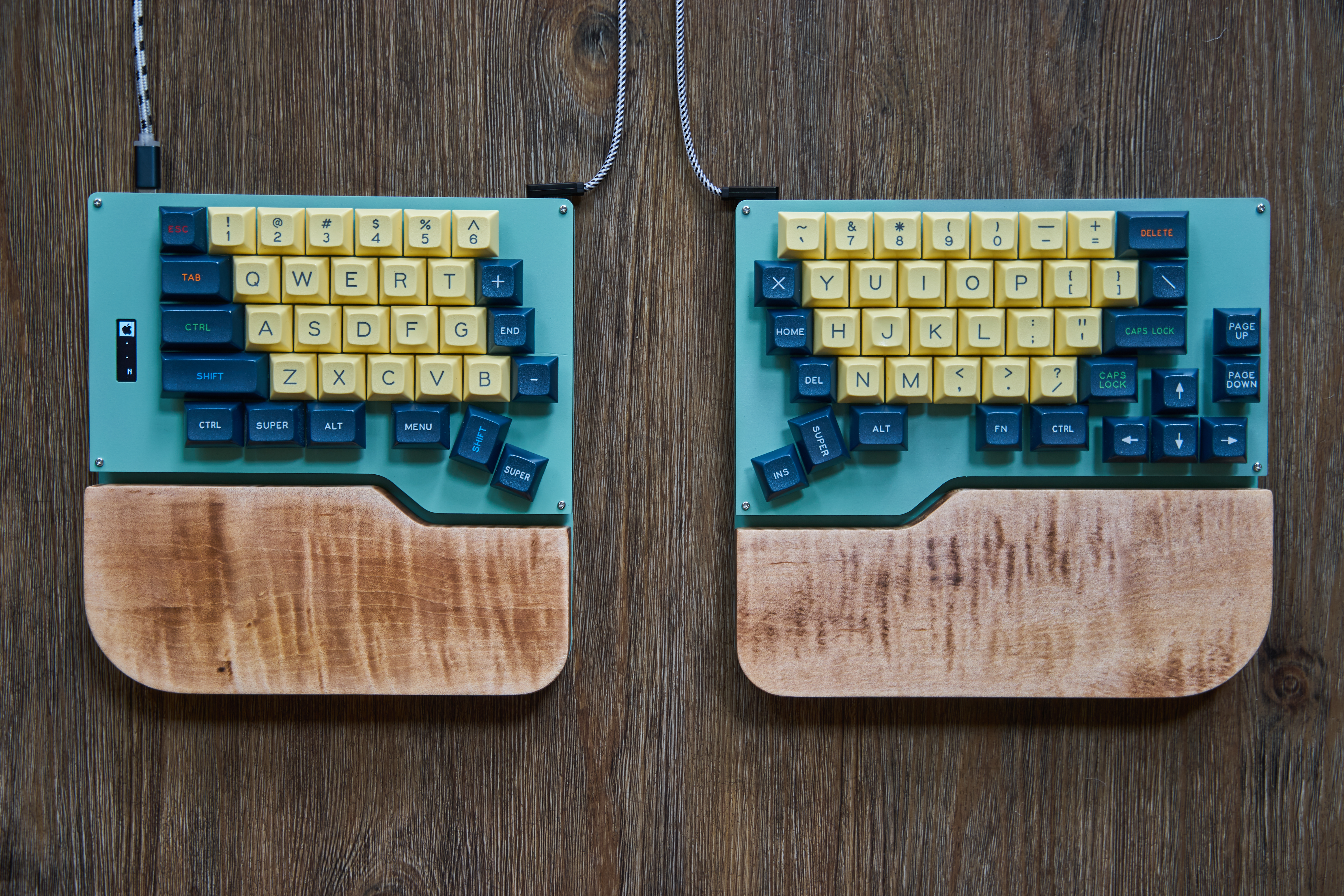
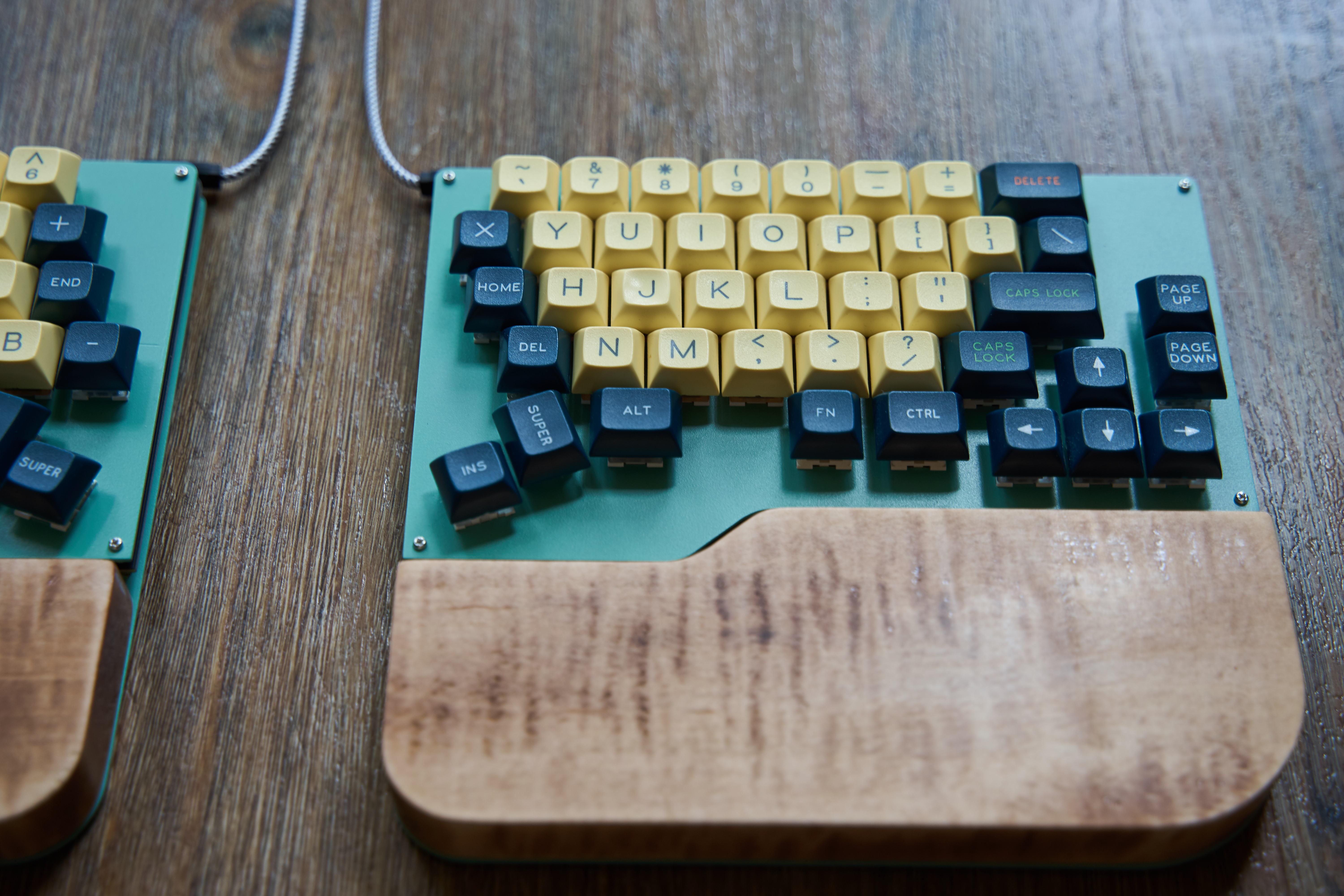
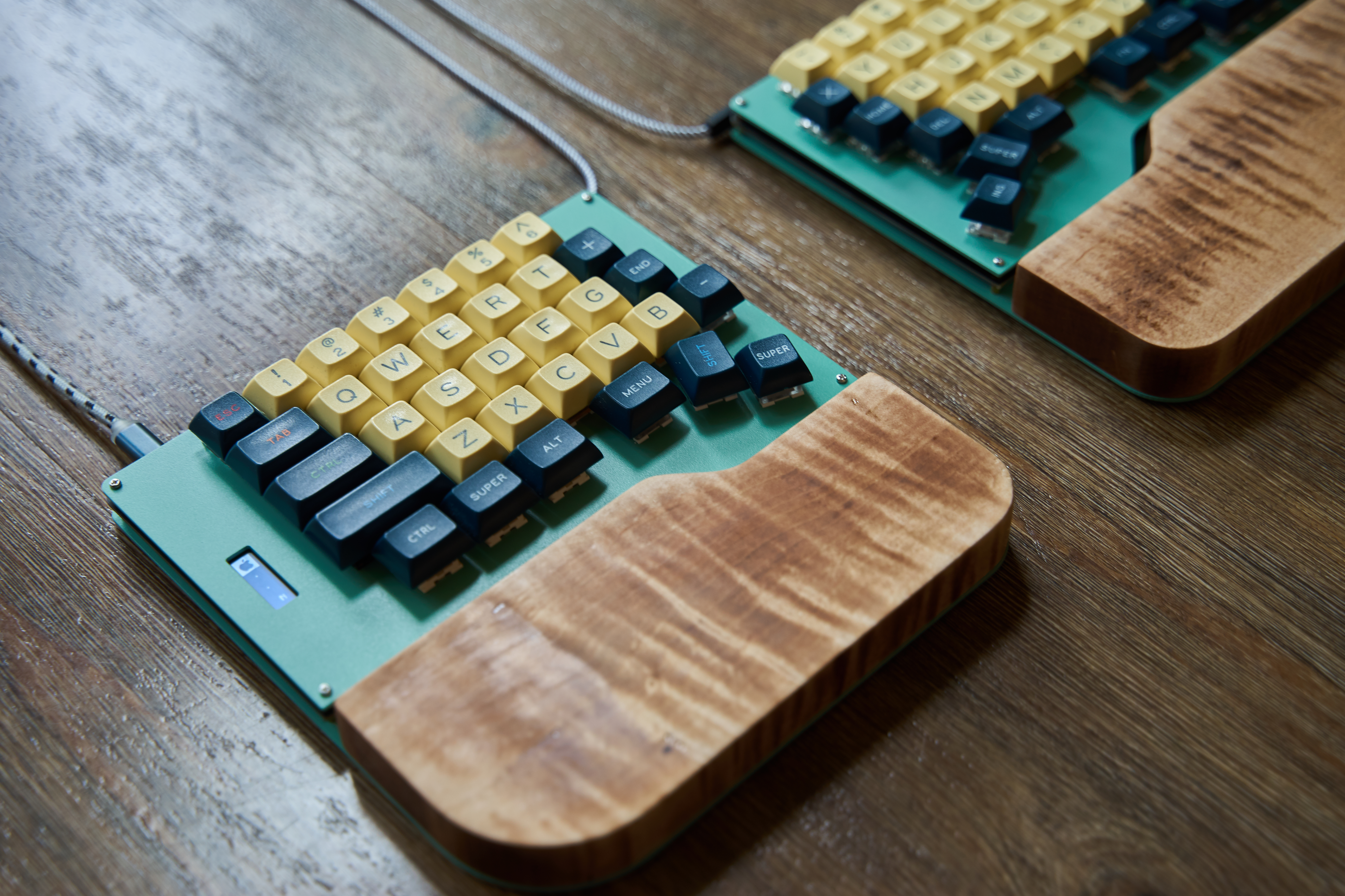
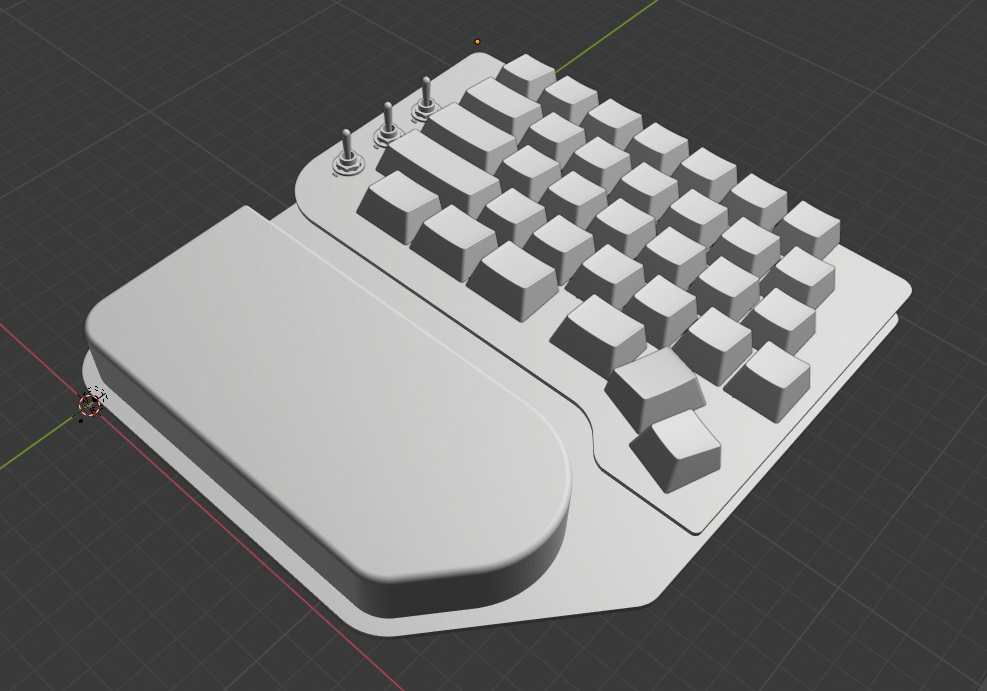
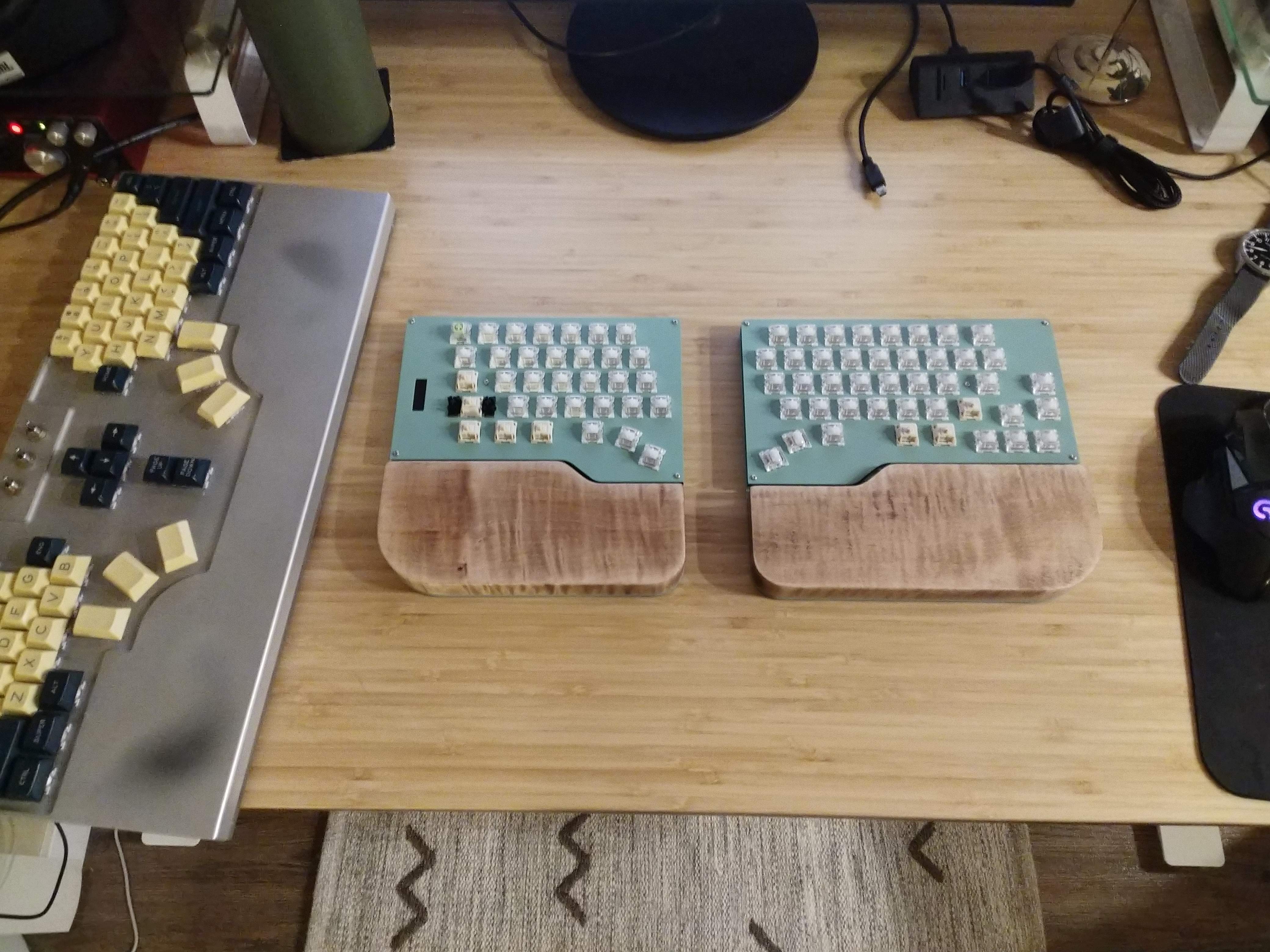
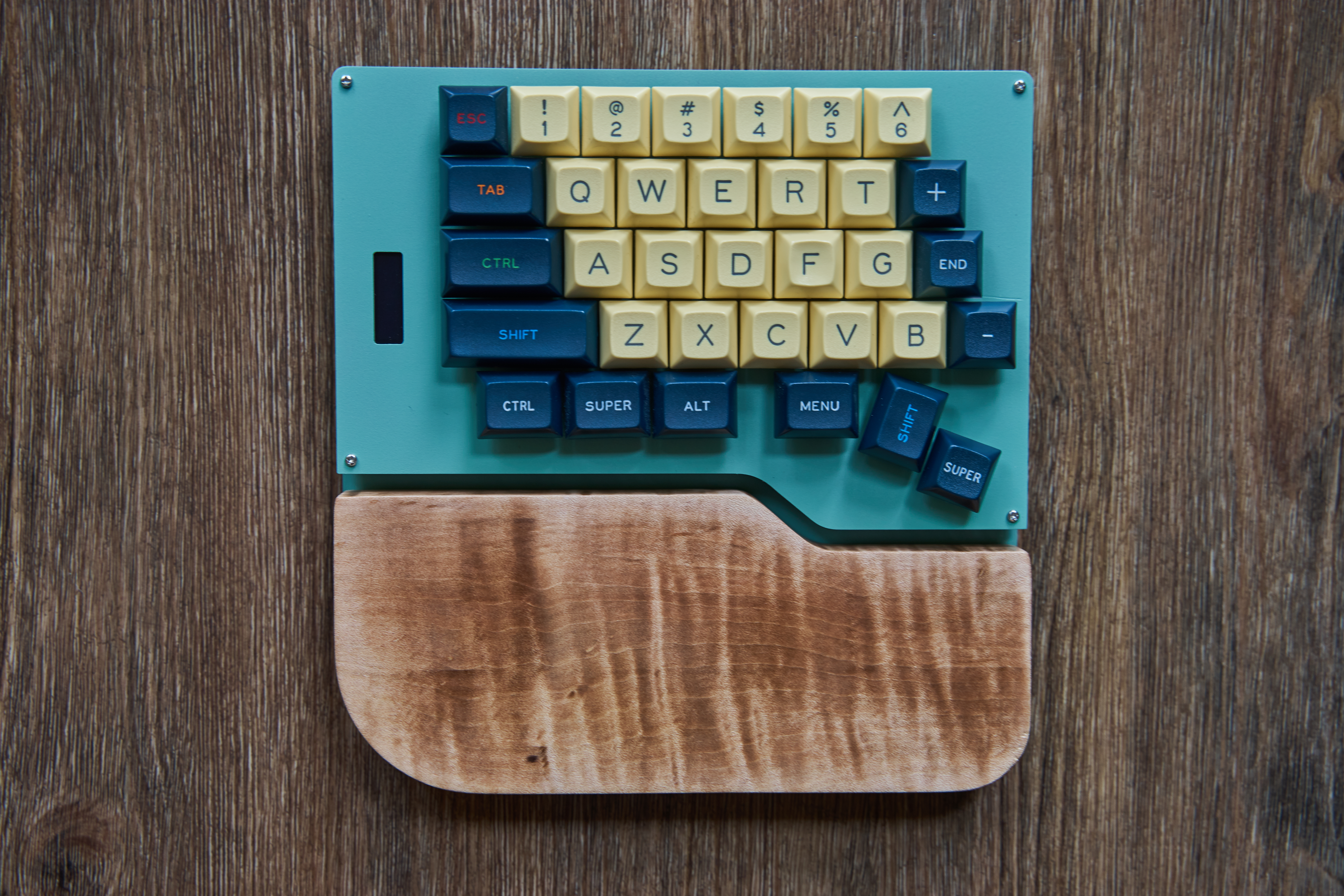
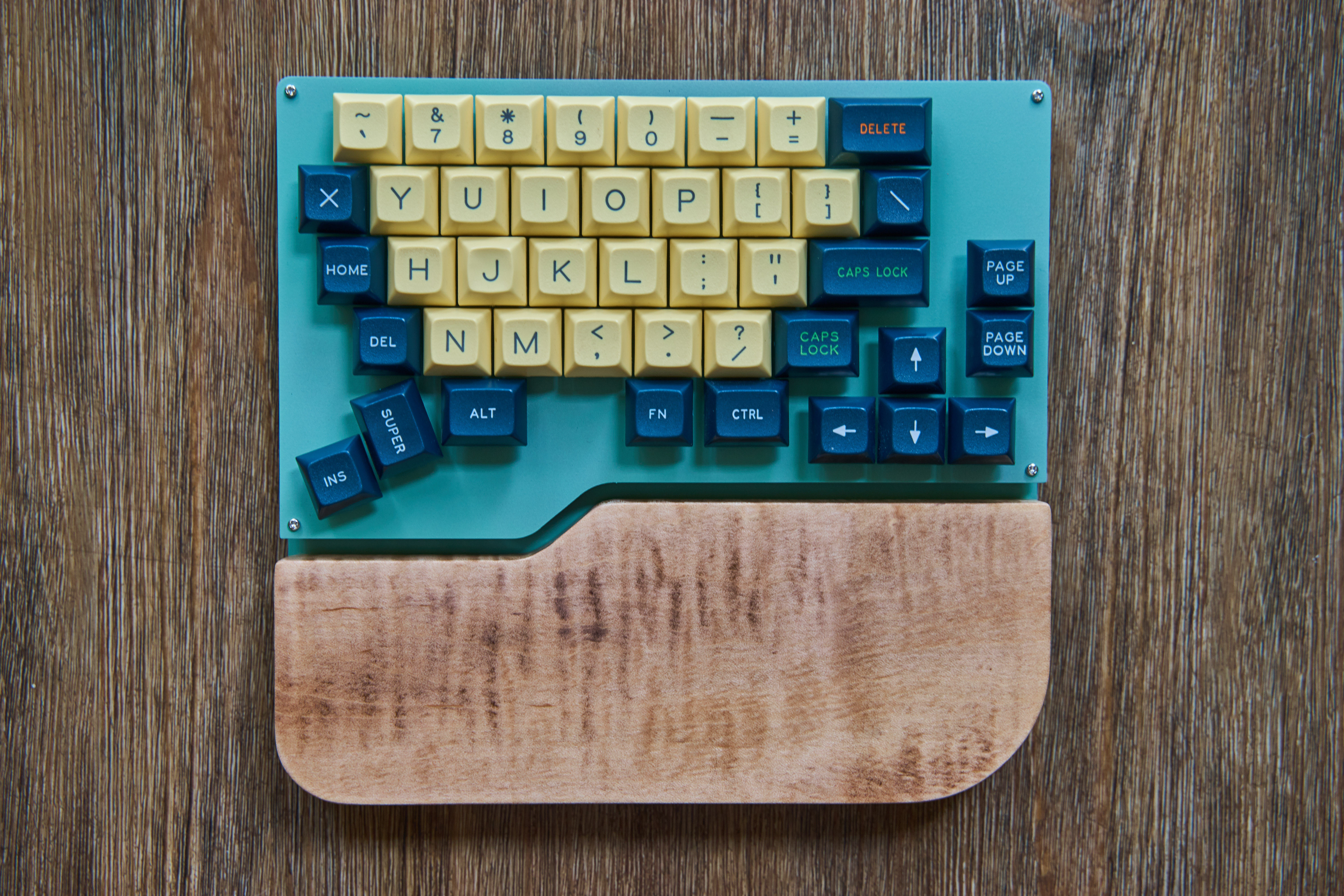
Pictured above is a finished Ellipsis Split keyboard. The Split is a spiritual successor to the Ellipsis, my previous attempt at making a custom keyboard.
Note: I don’t actually have two capslock keys - I just ran out of keycaps that fit lol. In fact, most of the nonstandard keys are mislabeled simply because I just needed keycaps that fit.
The initial design phase for the Split started in early December 2019, and there were a couple breaks here and there for holidays, other projects, work, etc. Designs were sent out to be manufactured early May 2020, and painting / assembly began about two weeks after. The keyboard was finished on June 11th, 2020.
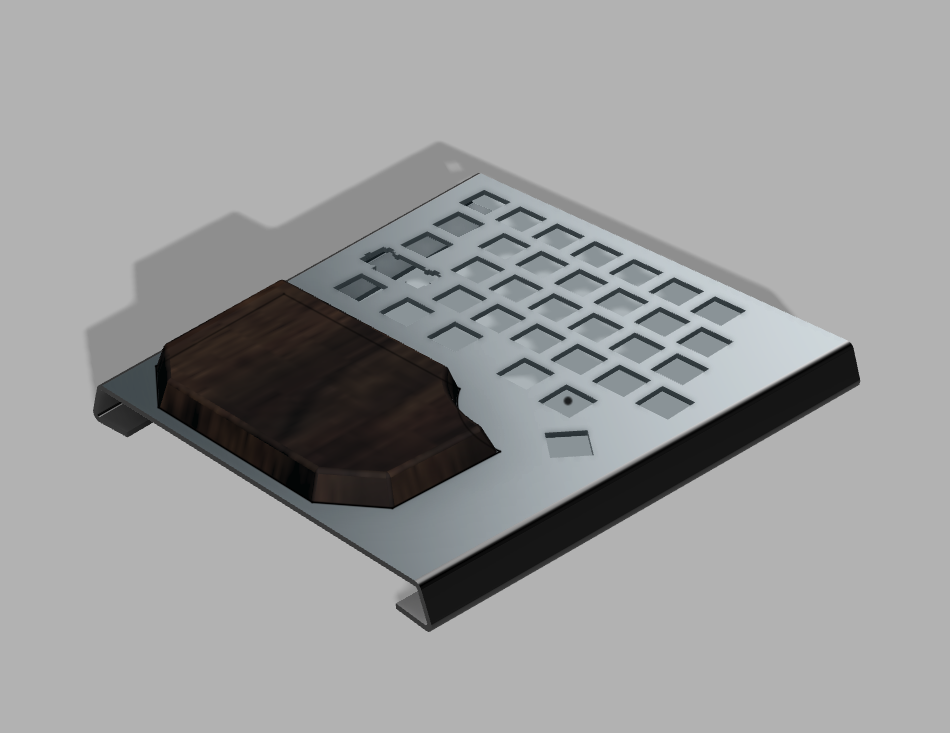
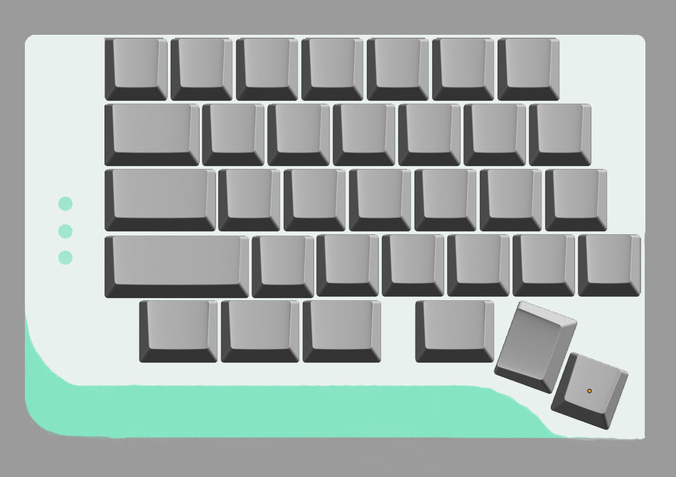
These are various prototype designs from fairly early in the process. I was pretty set on an integrated wrist rest, but the last design shown here is a “short” version of the keyboard with a slightly overlapping bottom plate. The intention there would be to make the wrist rest optional for people who don’t like using them. I had some cool early designs for putting the wrist rest on rails so that it could be adjustable / removable. Doing so would’ve greatly increased the height / complexity of the keyboard though, so I scrapped them.
All designs until the very last had toggle switches instead of the screen that made it onto the final version. I really like the tactility of toggle switches for selecting keyboard modes / acting as a quick visual indicator of what mode you’re in, but I had a really hard time getting enough vertical clearance in the design to accommodate them. I wanted to keep the keyboard fairly slim so that the wrist rest wouldn’t have to be obnoxiously thick to be close to keycap-height. Adding toggle switches in would’ve made this really hard. Ultimately, I’m glad I switched to using a screen as a mode indicator instead, as this gives a lot more freedom to experiment with things after the fact in software.
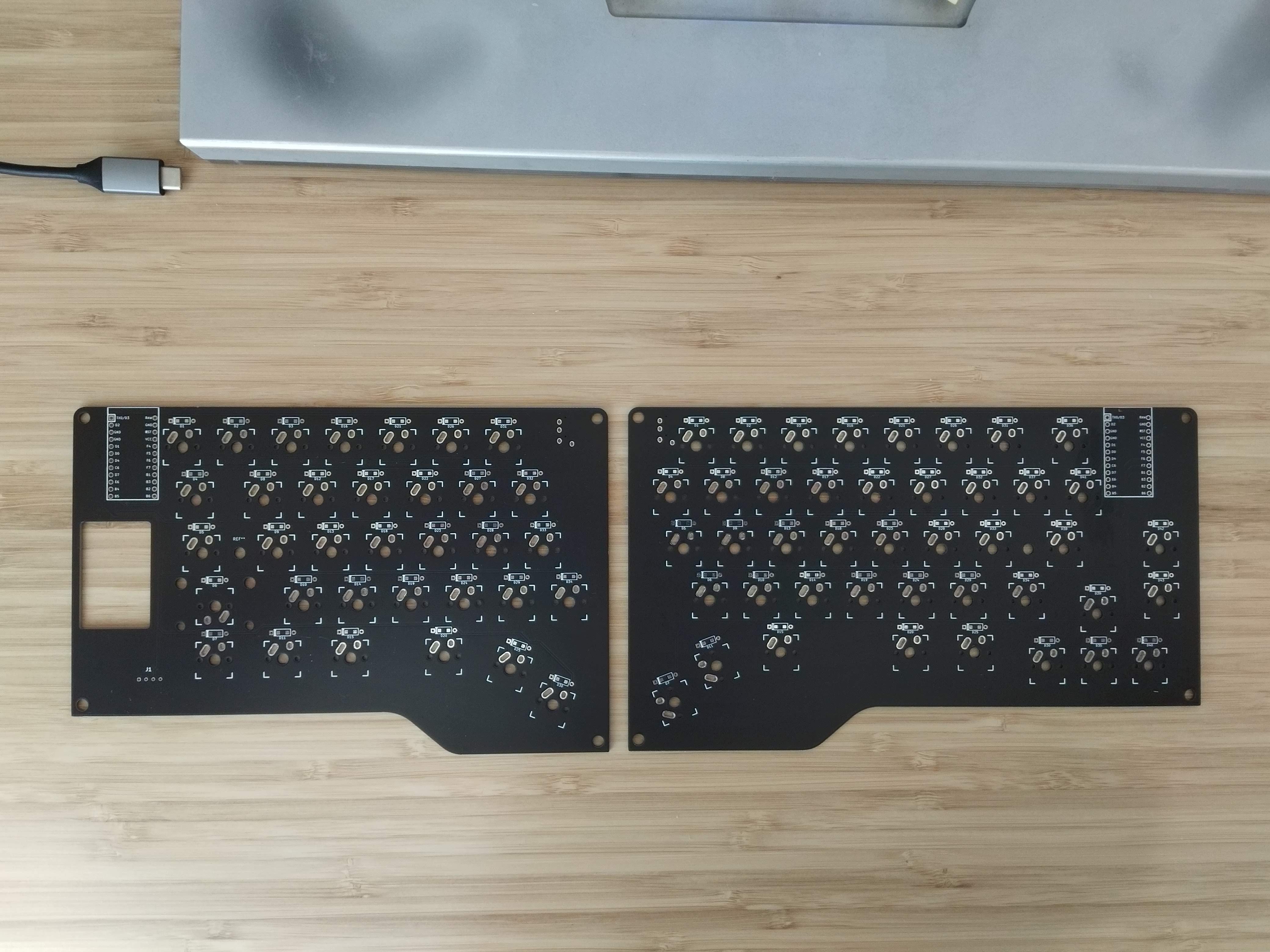
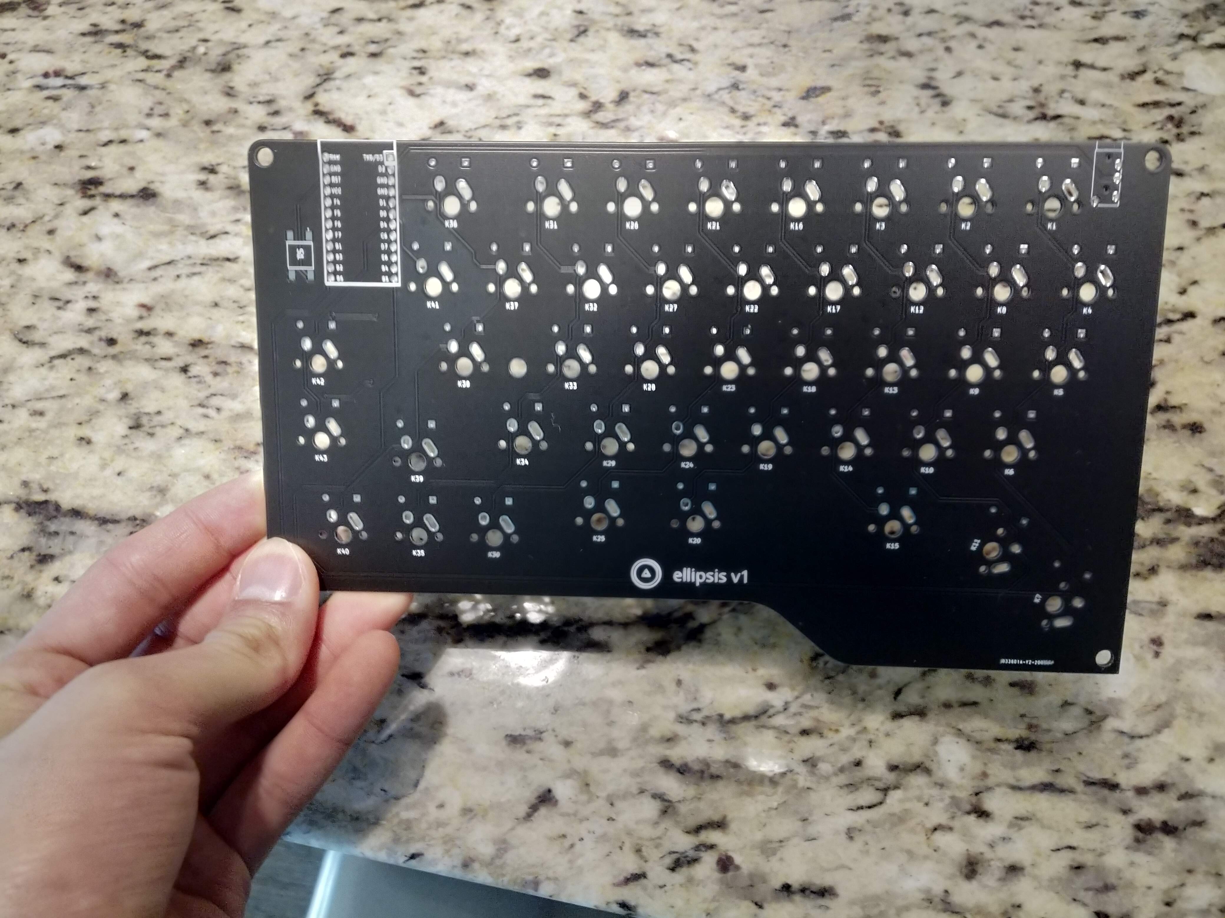
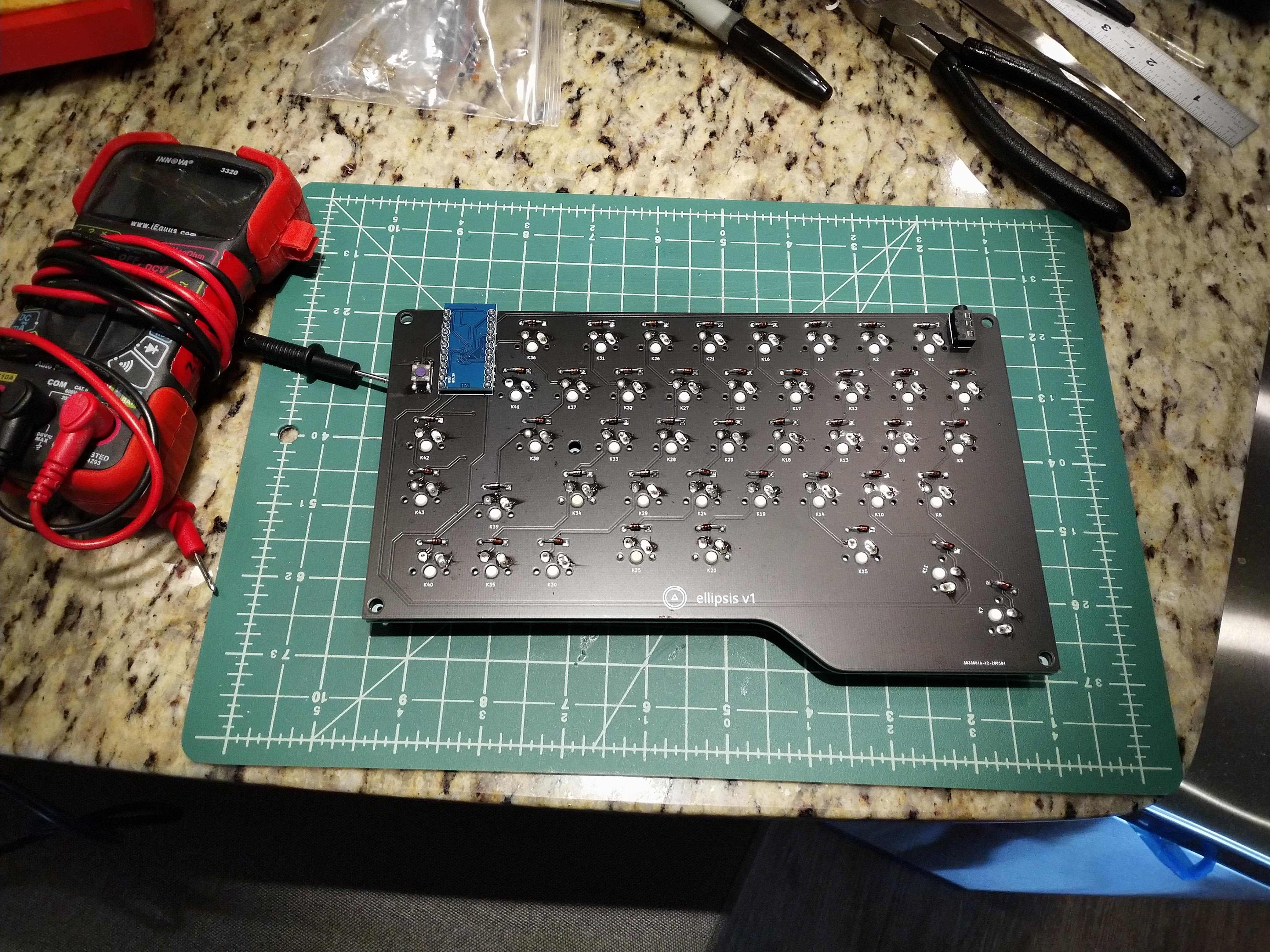
Here are the bare PCBs, which I ordered from JLCPCB. I think turnaround was about 5 days between me submitting the files to the boards arriving at my doorstep… from China. That’s insane. I paid for all of the cheapest options (around $40 for 5 left PCBs and 5 right PCBs), and they still managed to process my order, manufacture the parts, and ship them 6,500 miles in less than a week.
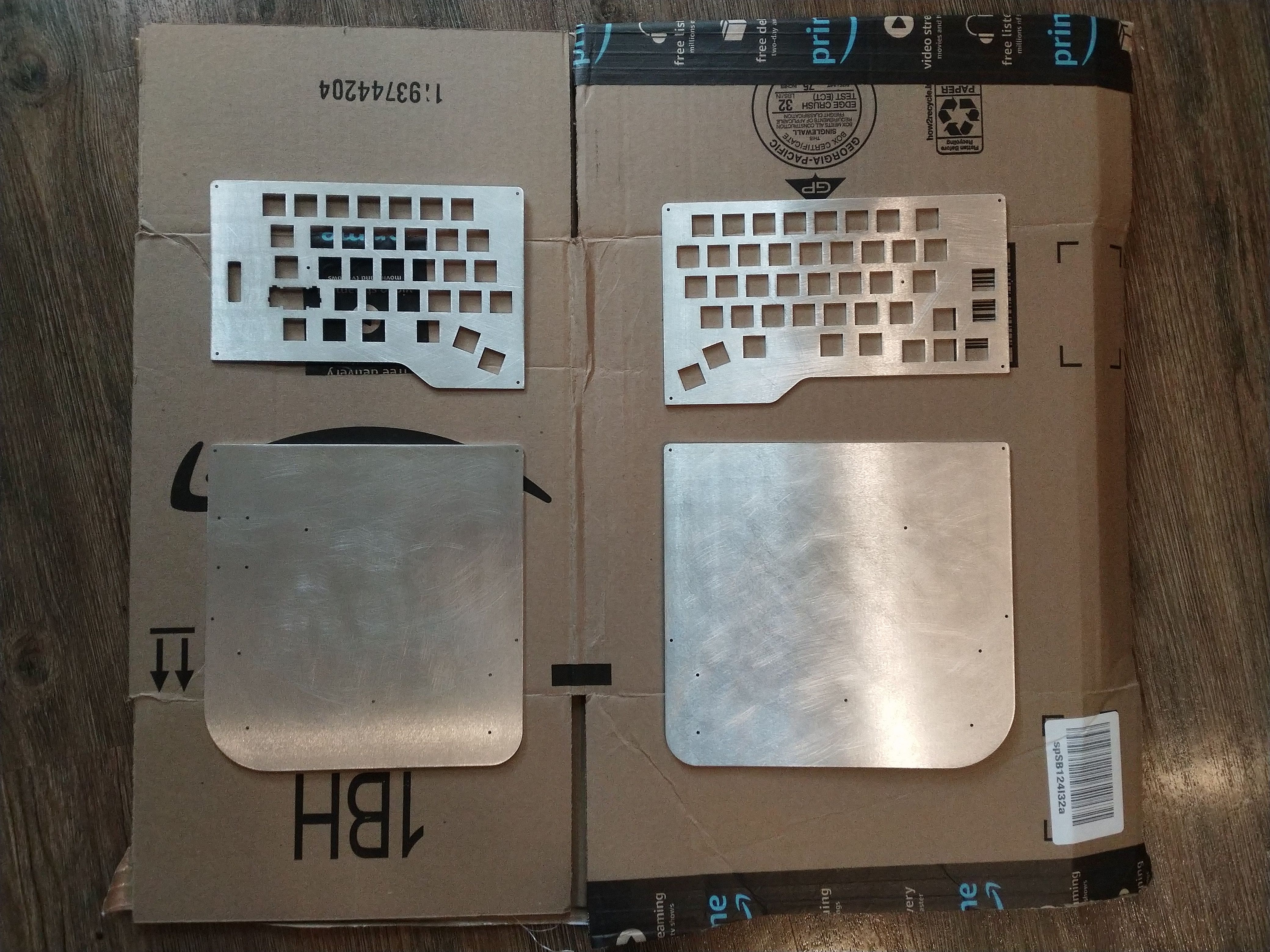
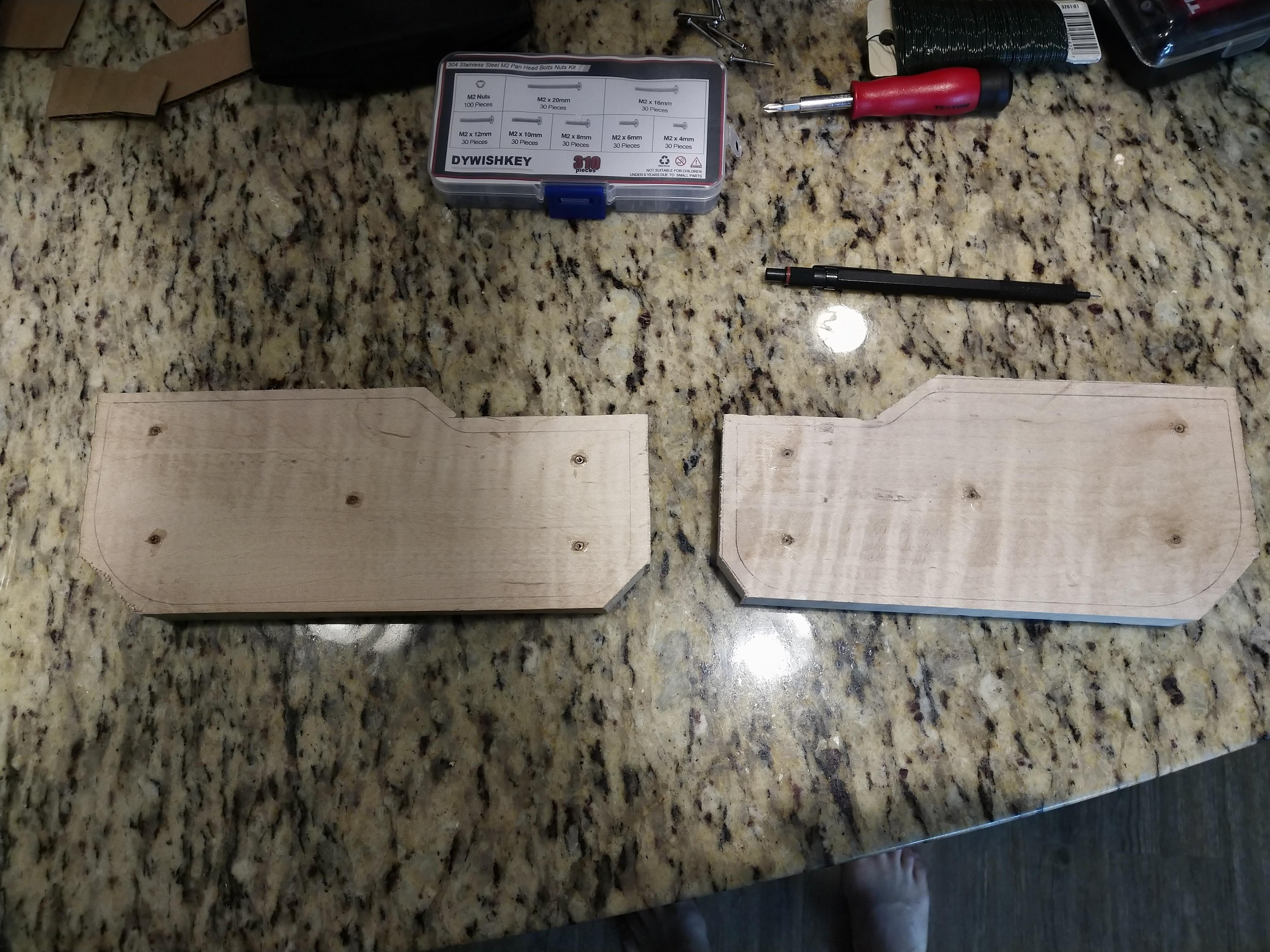
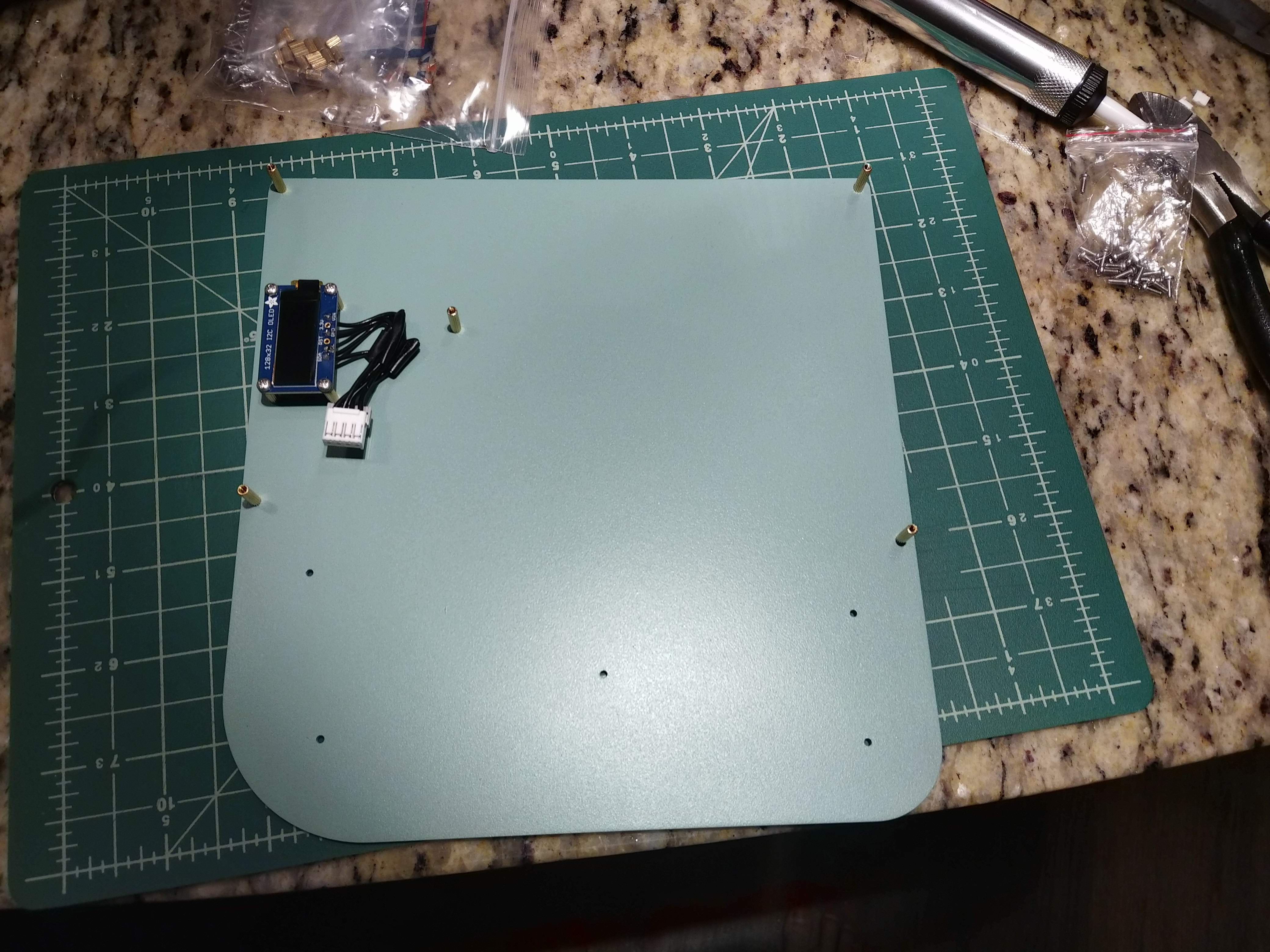
Here are the plates, which I got lasercut at Ponoko. These took much longer to get here than the PCBs, and were overall not super great quality. There’s some clear stairstepping on the larger rounded corners, and a small gouge on the left top plate. Pretty cheap though, and their website is easy to use.
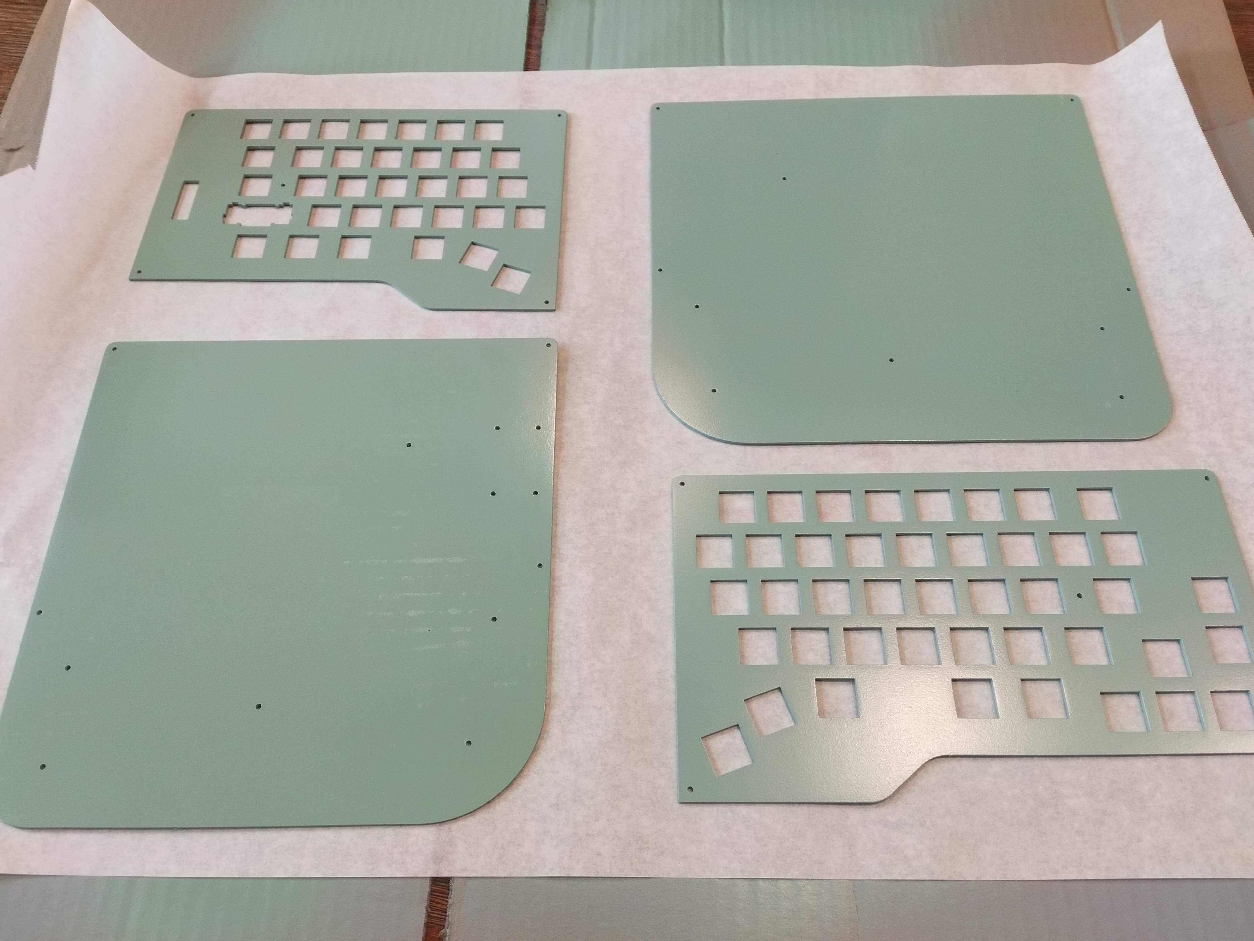
When it came time to paint, I used a rattle can acid-etch primer with Krylon Satin Jade for the basecoat color.
The first time I painted the plates, I messed up in a multitude of ways. I had them laying flat on a piece of cardboard on my patio on a windy day. It was also threatening to rain (as it does in Seattle), so I rushed through the process of spray painting them. As a result, you can see some marks on the bottom left plate where the paint dried onto the corrugated cardboard and ripped off. There are also spots where the wind blew debris onto the paint. That was dumb.
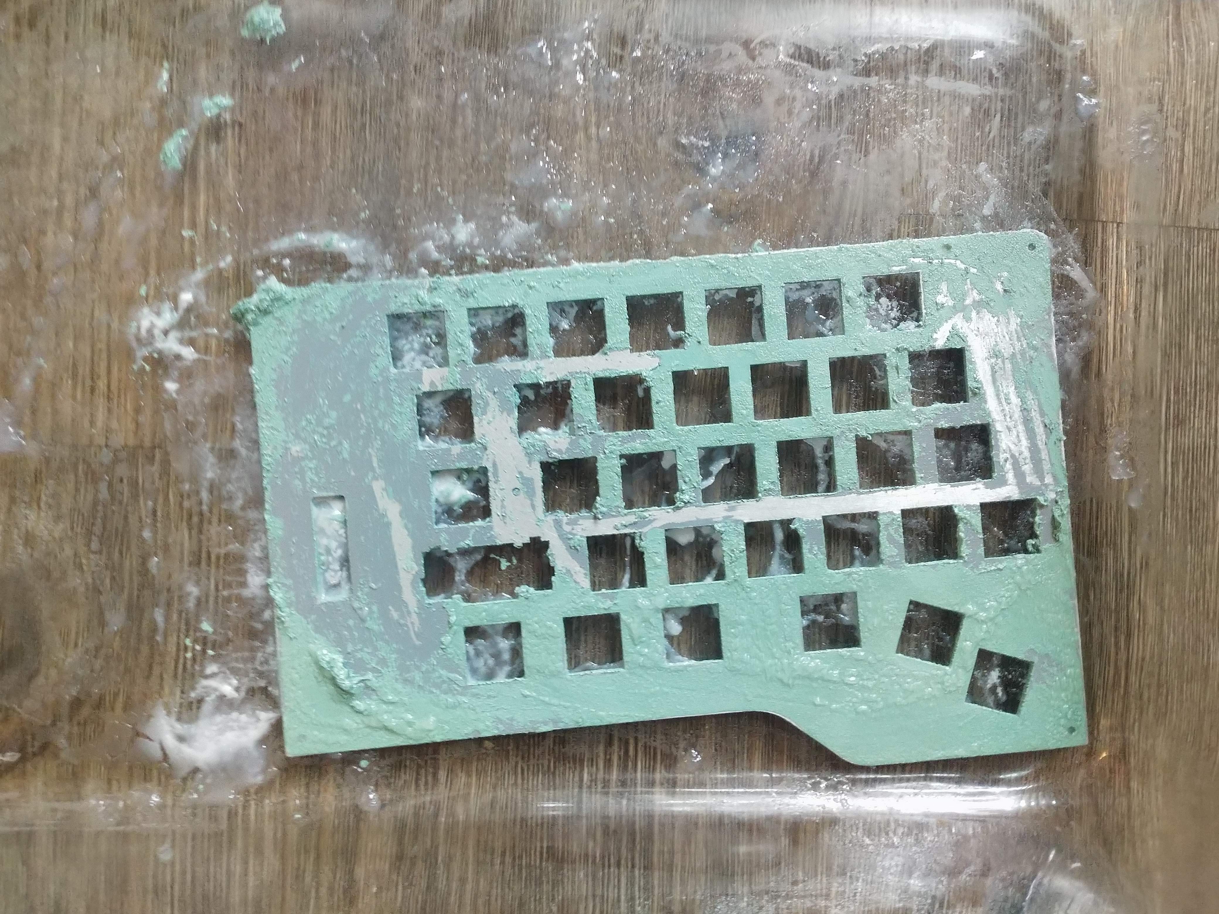
I also tried to clearcoat the plates only two days later. This was apparently not enough time for the base coat to cure, and the clearcoat had some terrible cracking / smudging. I ended up having to strip all of the paint and start over again. Painting apparently rewards patient people. I’m not a particularly patient person.
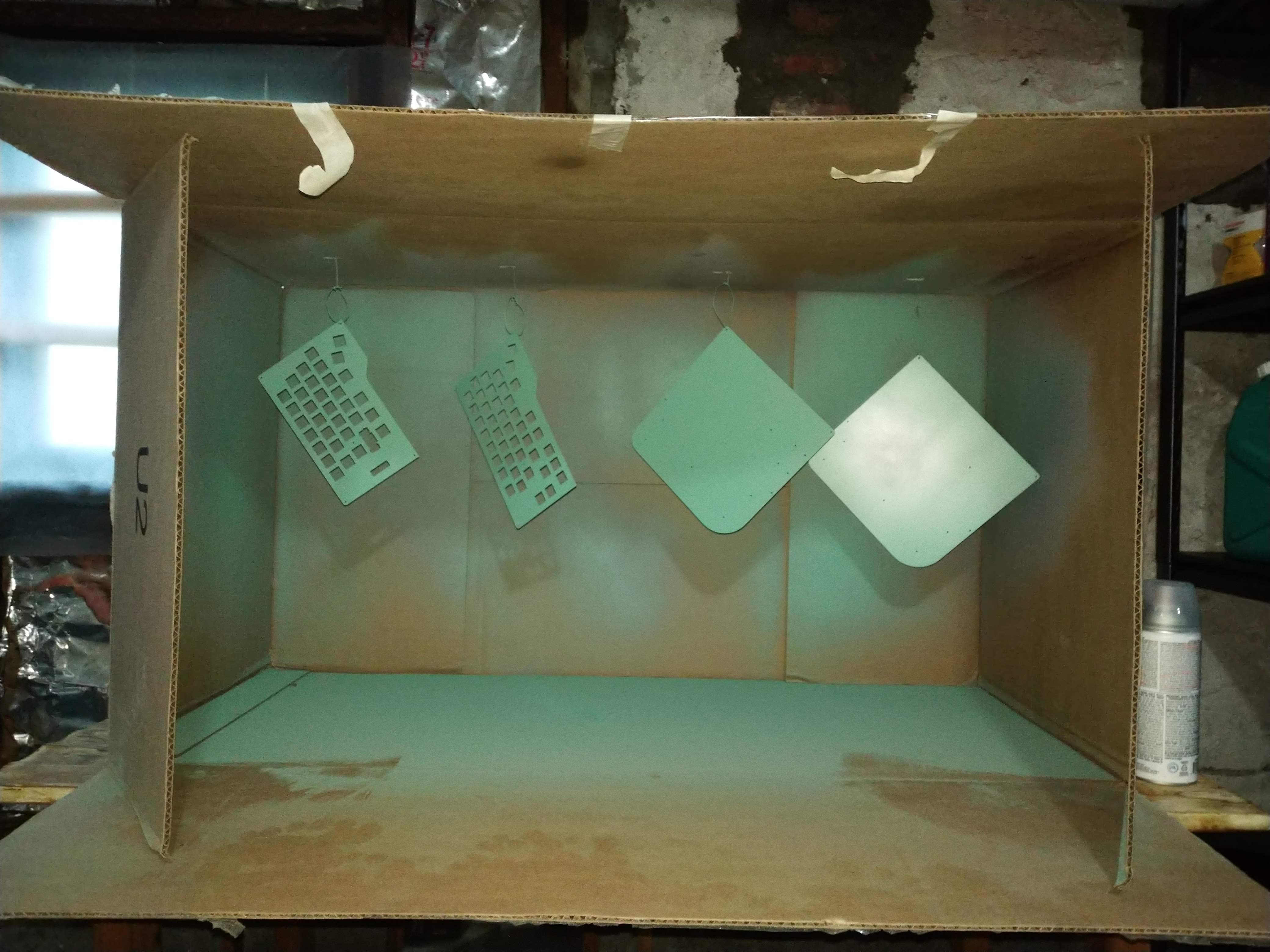
The second time around, I searched my apartment’s recycling bin for the largest box I could find, and created a little spray booth (and waited a week after painting the basecoat before spraying the clear. This worked very well.
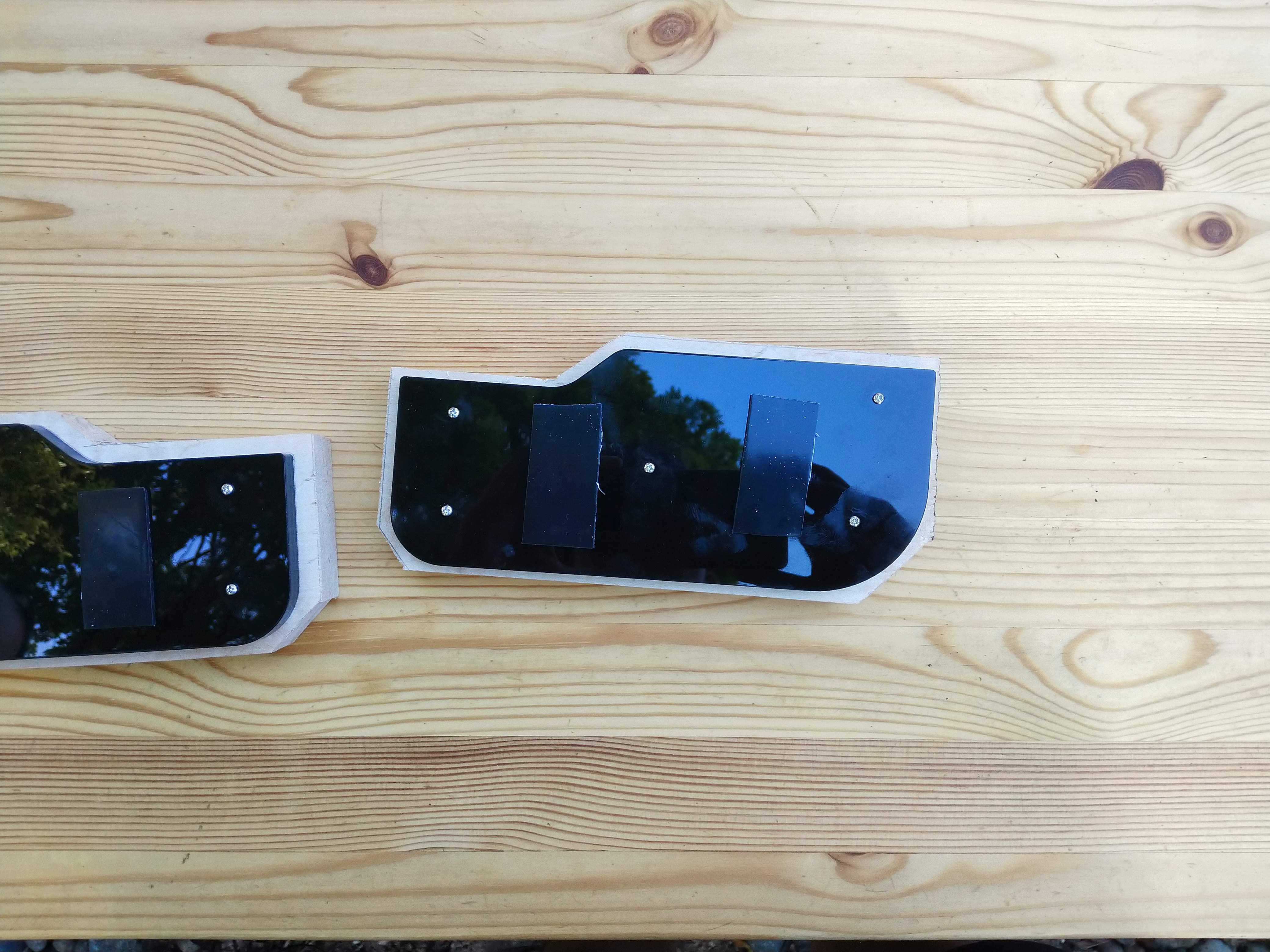
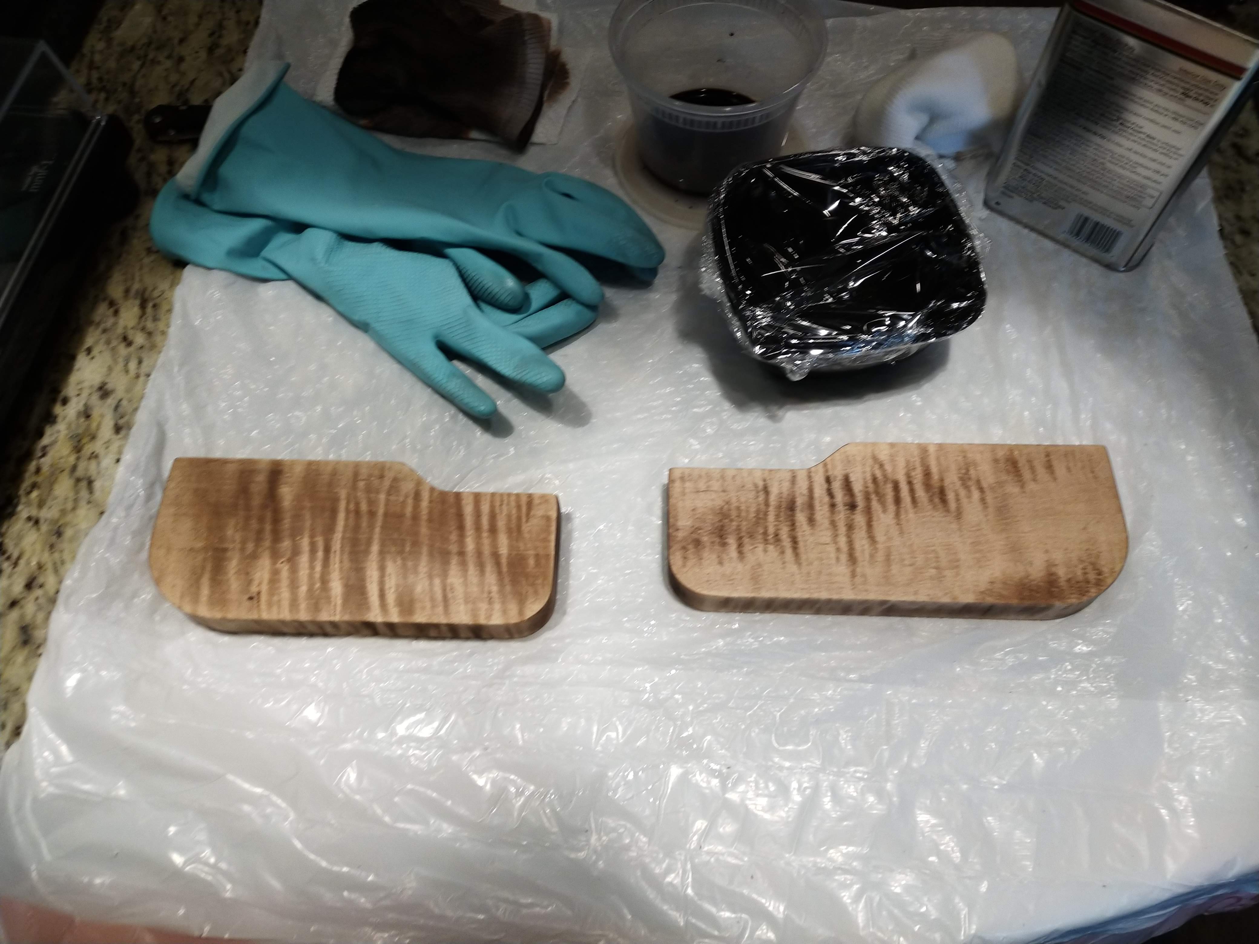
For the wrist rests, I got router templates (the black acrylic things screwed to the wood) laser cut by Ponoko as well. I roughed them out with a jigsaw, and then used a flush cut bit to route out the rest. Afterward, I dyed them, sanded back the dye to enhance the curls in the wood, and then applied a poly finish over the course of three days (I applied some patience learned in the process of painting the plates). The end result was… ok. I wouldn’t have minded a higher gloss finish, and it bothers me a little that the left side is darker than the right. Also, there was some gouging in the right side that I think was just there - I didn’t cause it. I should’ve been more careful about the part of the board that I cut the initial pieces from.
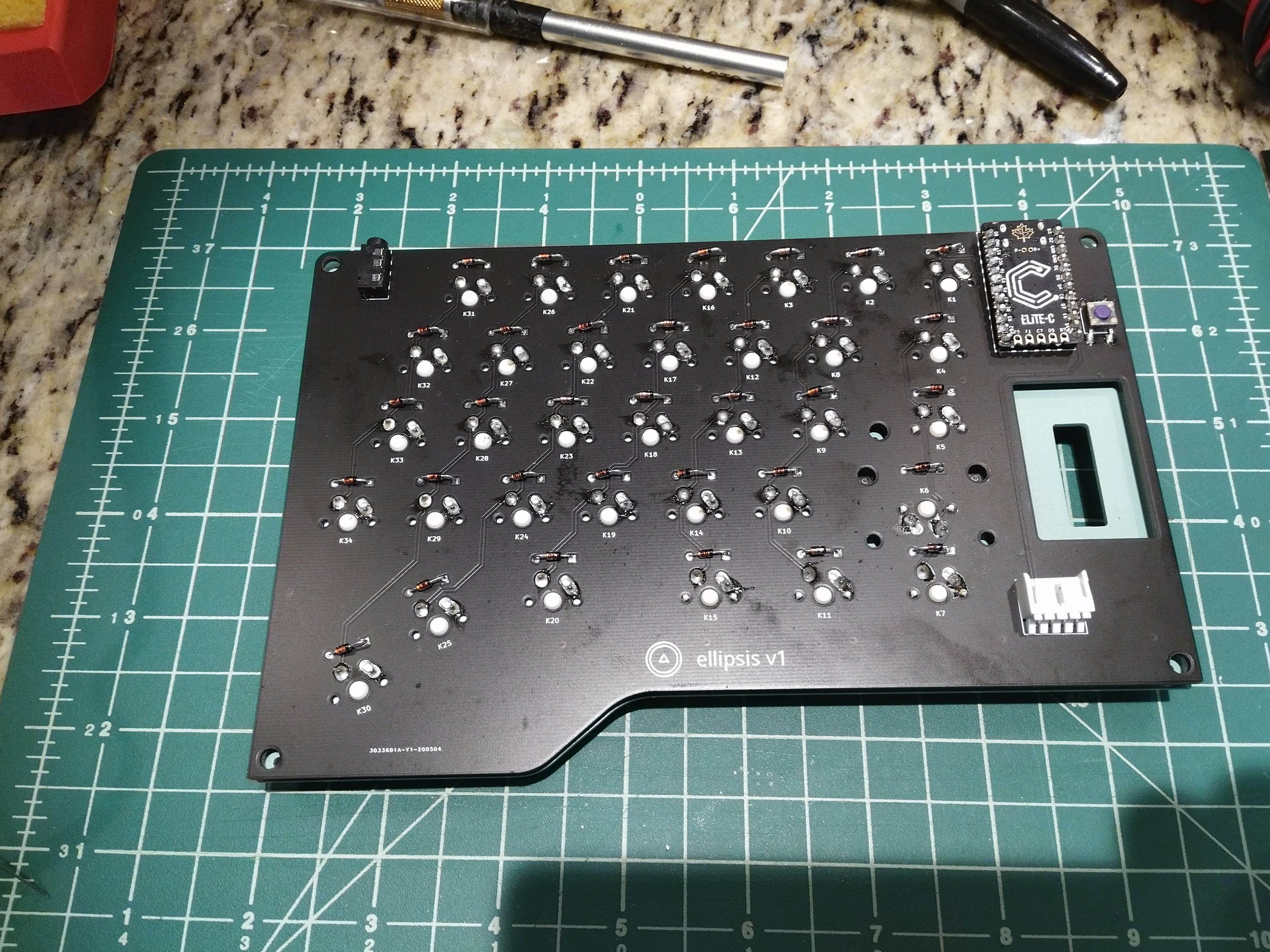
Note that the left half uses an elite-c instead of the pro micro used on the right half. This was to save a little bit of money while still getting usb-c on the half that I was planning on plugging into the computer.
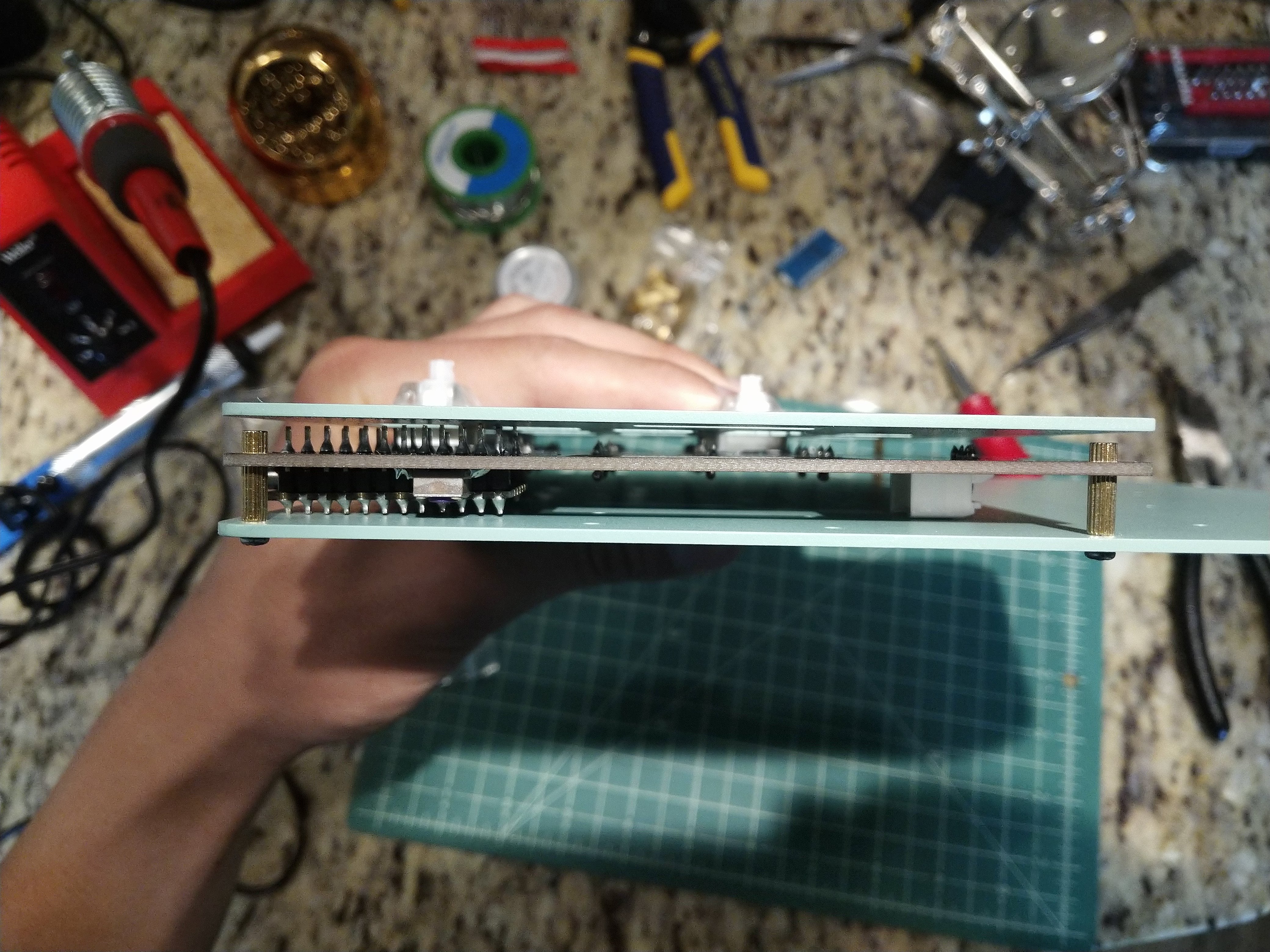
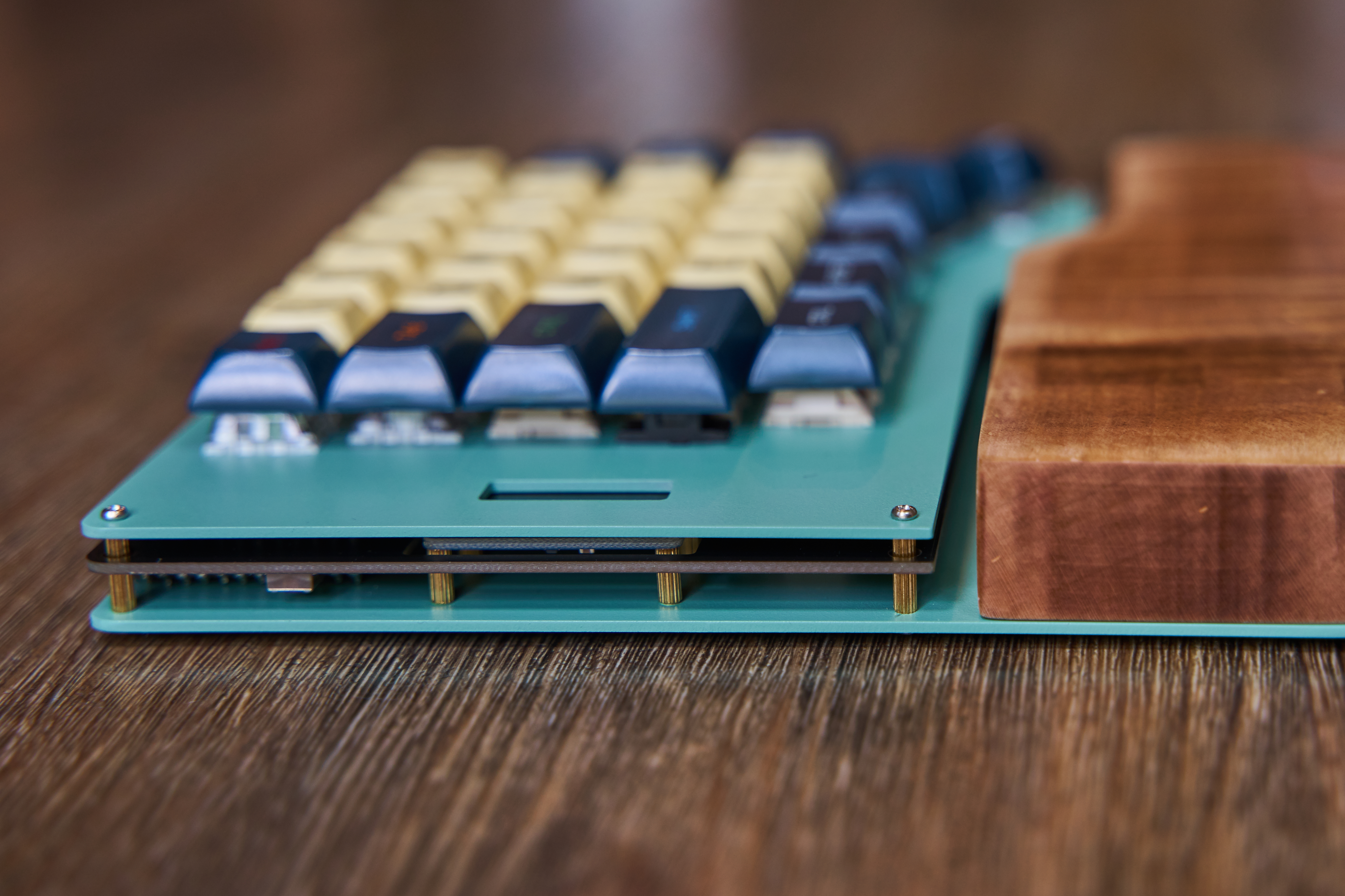
You can see here that the connector I used to attach the screen to the main board caused some clearance issues. I ended up cutting / filing it down until it fit. I probably should’ve just used 90 degree header pins or something instead of buying a connector like this.
The screen is mounted to the bottom plate, whereas the PCB itself is mounted to the top plate. This is what necessitated the use of the connector that caused the clearance issues in the first place. There’s enough clearance for the screen to be soldered directly onto the PCB, but I had a breakout board version - hence why there’s a big cutout in the main PCB.
Finished product - just before scavenging the keycaps from my old keyboard.
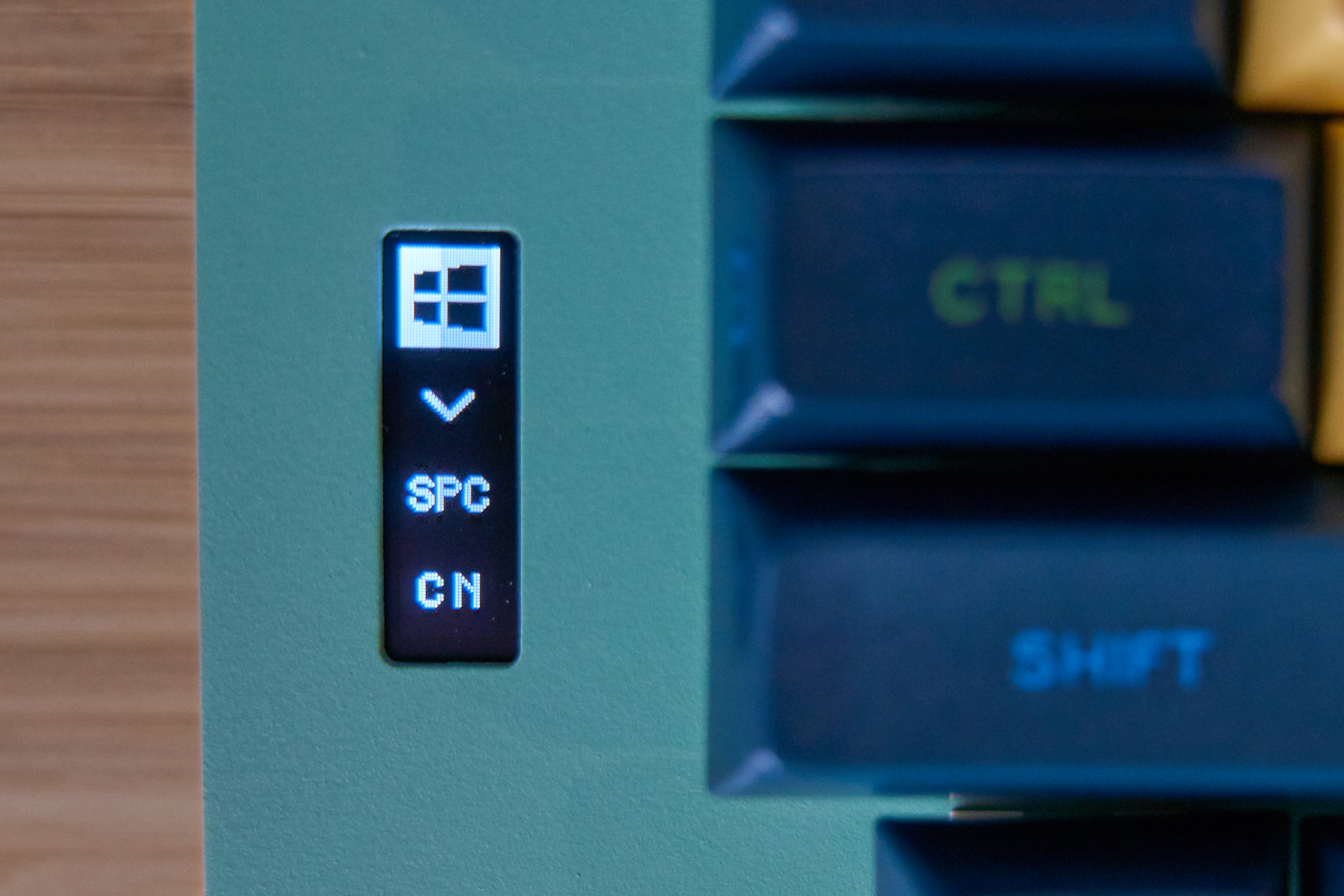
I use the screen to indicate:
- Mac vs Windows mode - changes my bound hotkeys (eg. fn-q is cmd-q on Mac, alt-f4 on windows).
- If the raise / lower fn keys are depressed.
- Whether the thumb clusters are in normal mode, game mode (moves the space bar to the left and adds a bindable f-key), or all spaces mode (so that a regular person can type without having to learn all the keys).
- Caps / Numlock.
That’s it!