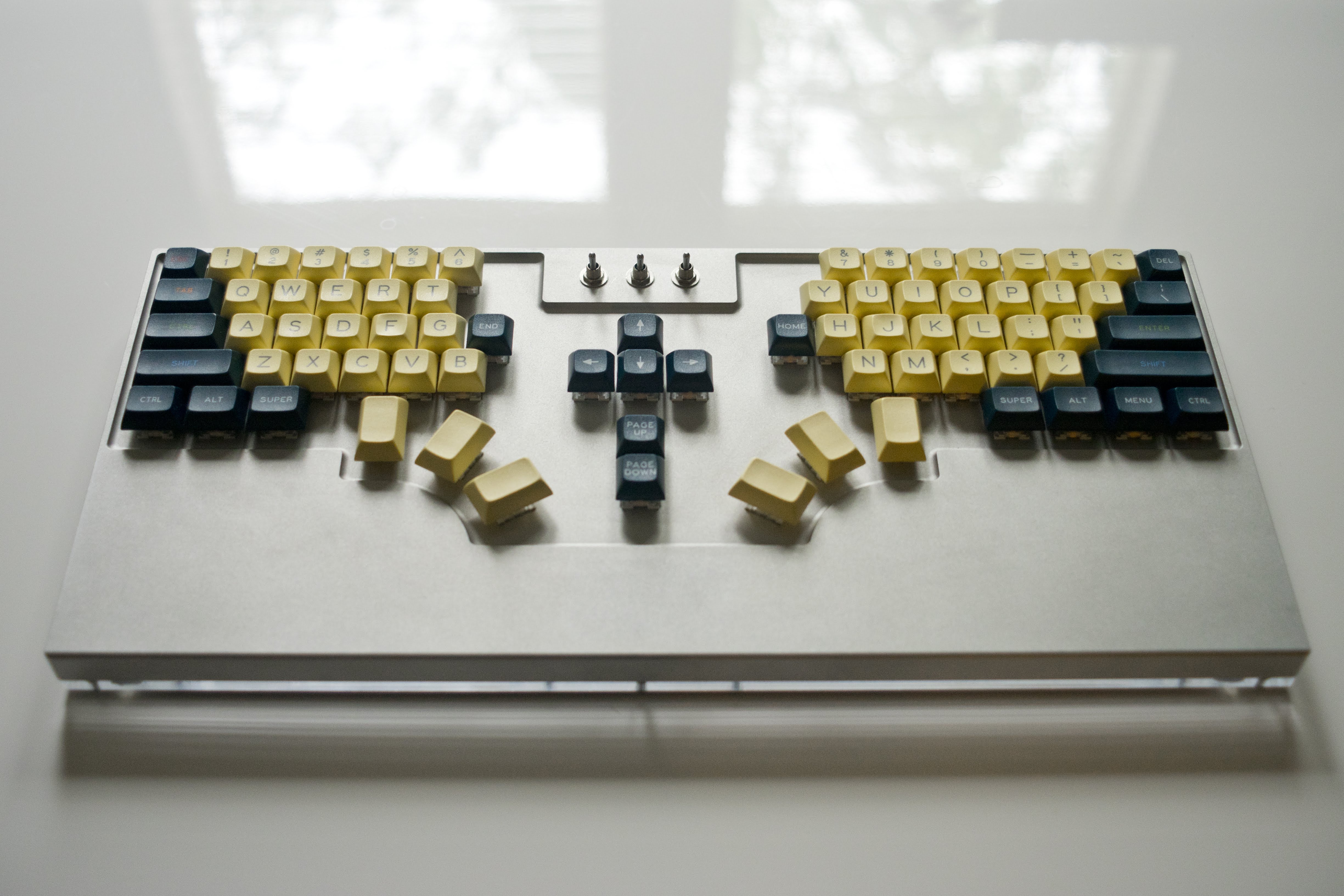
I made a mechanical keyboard! I call it the Ellipsis. This five-pound, way-too-expensive machined aluminum monstrosity was a lot of fun to make, and I wanted to share some thing that I learned along the way.
For the past couple years, I’ve been using mechanical keyboards with 60% layouts (no numpad, no arrow keys, no function row). There are lots of options available in this size, and it’s seemingly one of the most popular form factors among mechanical keyboard enthusiasts. However, after spending countless hours typing on keyboards of this size, I decided that I needed something just a little bit bigger. I really like the clean, compact look of 60% boards, but found myself constantly longing for dedicated arrow keys, pgup/pgdn/home/end, a dedicated tilde key, etc.
Additionally I wanted to experiment with putting more keys under my thumbs. The way most keyboards are laid out, you can only comfortably access three keys with your thumbs from the home position. Seems inefficient, right? There are keyboards like the Planck, Ergodox, and Kinesis Advantage2 that allow you to get more use out of your thumbs, but I had issues with all of them (Planck is too small, Ergodox is ortholinear, Kinesis is… just too weird looking).
Finally, I wanted a keyboard that I could reflash with my own firmware / layouts. This was another strike against the Kinesis, and really only left me with the option of building a keyboard from scratch. I searched for a long time for a DIY kit that fit the bill, but couldn’t find anything. So, I decided to go fully custom.
Designing the Layout
The first thing I did was design the key layout for the keyboard. As this was the main thing preventing me from just buying an existing model, I wanted to make sure I got this right. If I had more time and/or patience, I probably would’ve 3D printed some prototypes to test key placement and whatnot. However, I found it much cheaper and only slightly less effective to just draw a scale version of the layout on pieces of cardboard and move things around until they felt right. Once I had rough dimensions from this process, I started drawing everything out in Adobe Illustrator.
There’s a great, open-source tool for creating layouts of keyboard designs at keyboard-layout-editor.com. Unfortunately, my layout required all sorts of weird angles and precise dimensions, hence the decision to do most of the work in Illustrator. I did, however, export a mockup from the layout editor into a vector format, which I then used as a starting point for my Illustrator file. This was handy for making sure the keyswitch and stabilizer footprints were correctly sized and spaced.
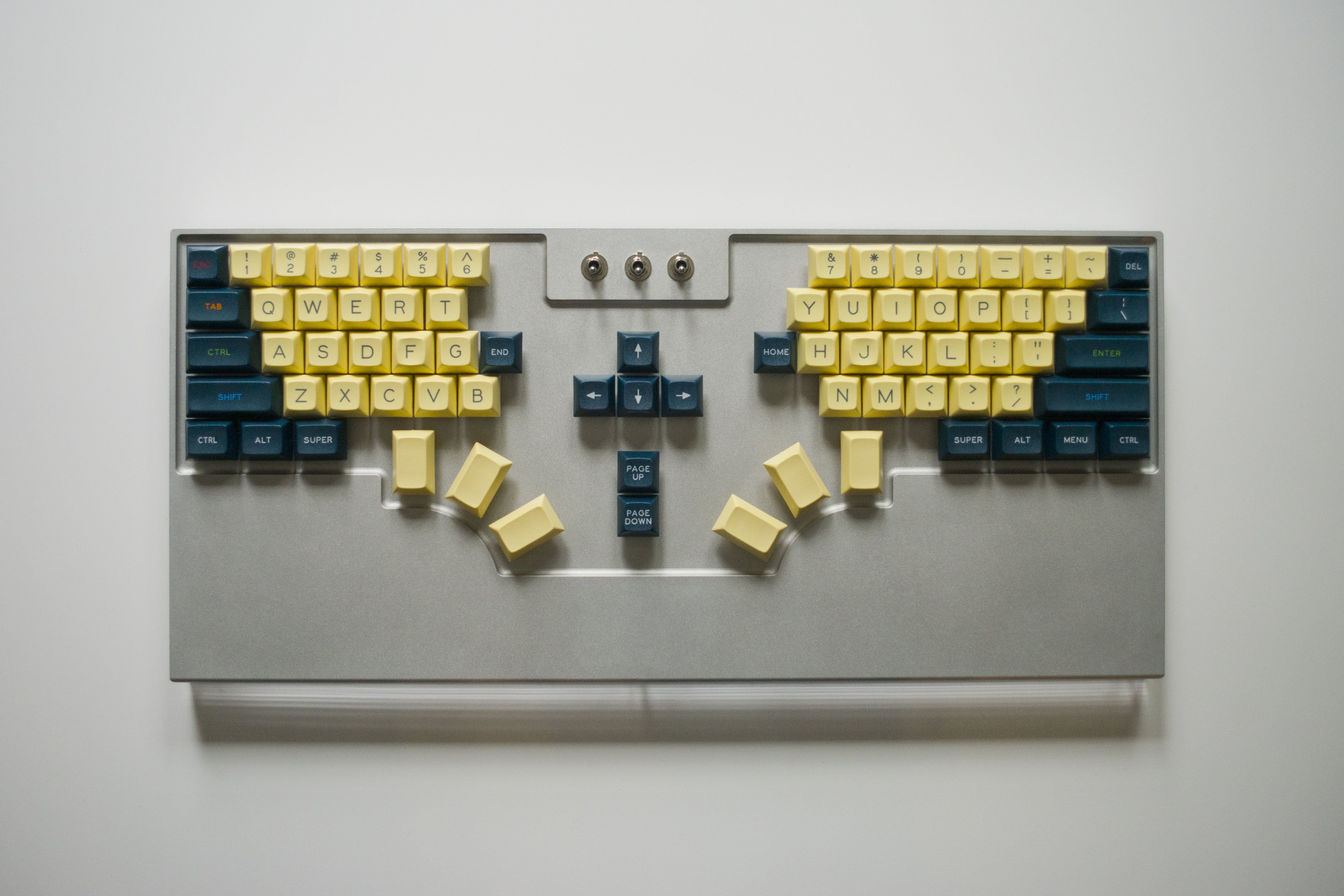
Here’s a top-down picture of the keyboard so you can get a sense of the final layout. Most of the keys are in their normal places, with a few notable exceptions. In the number row, notice that the escape key has taken the place of tilde, and the backspace key has been split into tilde and delete. I have control mapped to where capslock normally is, and also have the home and end keys at the ends of that row, in easy reach of the index fingers. This is made possible by the fact that I split the keyboard into two halves, which I figured would let me position my shoulders and wrists in a bit wider and more natural way. The arrow keys and pgup/pgdn also take advantage of this fact, and can be accessed easily by both hands as a result. Interestingly enough, I seem to have placed the ‘B’ key on the wrong side of the split (I apparently used to hit it with my right hand), but adapted to that pretty quickly. Finally, the “MENU” key on the right side acts as a function key, which turns certain keys into media player controls, volume, etc.
For the thumb keys, my current (macOS) mapping from left to right is as follows: meta, shift, alt, enter, space, backspace. The left and middle toggle switches at the top of the keyboard let me switch between different layouts. When switched to the “up” position, the left toggle moves the enter/space/backspace cluster to the left thumb keys so that you can use the keyboard with one hand for gaming. The middle toggle is a three-position for Linux, macOS, and Windows layouts, though I realized after the fact that Linux and Windows keyboards have the same layout… The right switch is a momentary that resets the Teensy so you can flash new firmware.
Once the layout was done and triple-checked, I was ready to think about actually making the thing.
Change of Plans
Most mechanical keyboard kits come in two or three parts. Usually, the keyswitches are mounted on a thin metal plate. The switch contacts are then usually soldered into a PCB. Some keyboards eschew the plate entirely and just mount the switches directly to a PCB. Finally, this assembly is mounted into a plastic/metal/wooden case to protect the electrical underside. There are exceptions, of course, but this is a proven, sturdy, cheap way to make a keyboard. This is initially how I planned on making my keyboard. I was going to waterjet a plate with my custom layout, then get someone to CNC mill a nice case out of wood.
I ran into some issues with this. Getting the plate waterjet was no problem. There are plenty of services online that’ll do it for cheap. As I researched more, though, I began to realize that making a nice wooden case could be problematic. First of all, sourcing a single slab of wood big + thick enough to machine the case out of would’ve been tricky and somewhat expensive. I guess there was the option to buy a piece of wooden countertop and machine that. Actually, I could’ve gotten a guitar body blank as well… Looking back, maybe I didn’t spend enough time thinking about this. But I digress. My other concern was with getting someone to machine the specific piece of wood that I had picked out. Most of the big online CNC milling services let you pick from a limited set of stock materials, so I wasn’t sure I’d be able to find a place where I could just send in my own stock and have someone machine it. In the end, though, this is exactly what I ended up doing with the case I made, so turns out this wasn’t actually an issue either. So I guess the lesson here is that you can definitely get a custom machined wooden case if you want one. I was just worrying too much. Worth noting that you can also contact your local makerspace to see about doing the machining yourself, but that’s a path I didn’t want to go down for various reasons (laziness, mostly).
As I was considering all these concerns, I started to realize that most of the custom CNC places mostly work with machining metal, and that when all was said and done, getting something machined out of metal isn’t much more expensive than getting it machined out of wood (at this quantity, most of the cost is in labor and machine setup, not materials). So I started thinking about all the cool ways I could change my design with a metal case. It struck me that I could do away with the plate entirely by just machining the holes for the keyswitches directly out of the case - much like a “unibody” MacBook Pro. I thought that idea was really cool, so I set out to design my very own “unibody” aluminum mechanical keyboard.
Designing the Case
Now set on designing a very complex case, I needed to make the switch from Illustrator, a 2D graphics program, to a more serious 3D CAD tool. I had dabbled in CAD stuff before, but only on friends’ computers. So, I needed to find some software I could use on my own machine. I realized a little too late that Fusion 360 is free for hobbyists, which would’ve probably worked just fine. In the end, though, I ended up using FreeCAD for all of my design work. I’m not sure this was the best decision. It’s great that it’s free and open-source, but, as is often the case with free software, it lacks a lot of the polish of commercial offerings. Sometimes it’s just downright buggy. More on that later.
This might not be a popular opinion among keyboard snobs, but I actually really like my Late 2013 MacBook Pro’s keyboard ergonomics. I like having my keys flat on the same plane as my wrists. This is in stark contrast with all the other mechanical keyboards I own, which are angled slightly upwards with a >20mm vertical distance between the tops of the keys and the desk. Additionally, all of my other keyboards have sculpted keycap profiles, which means that the number key row is the tallest, and the keys are sloped in a sort of concave way that’s supposed to be ergonomic (but actually just feels really weird to me). Take a look at the DCS and OEM profiles in this diagram - those are both sculpted profiles, and comparable to what I was using before this.
With this in mind, I designed the case with a couple special features. The most prominent of these features is the integrated wrist rest, the dimensions of which are based heavily on the MacBook’s. Unlike the MacBook, however, the entire bottom edge of the keyboard is filleted so that it doesn’t cut into your wrists, as I’ve found my MacBook sometimes does when typing at a certain angle. I also inset the surface where the keyswitches are mounted so that it’s a couple millimeters lower than the plane of the wrist rests. This is so that the tops of the keycaps are a little closer to being flush with the rest of the case. Because we’re working with tall mechanical keyswitches + keycaps instead of chiclet keys, it’s not feasible to get them all the way flush, but the inset definitely helps a little. Finally, I made sure to buy a set of DSA profile keycaps, which are not sculpted, and instead have a consistent height across all rows (see linked diagram above to compare them to sculpted profiles).
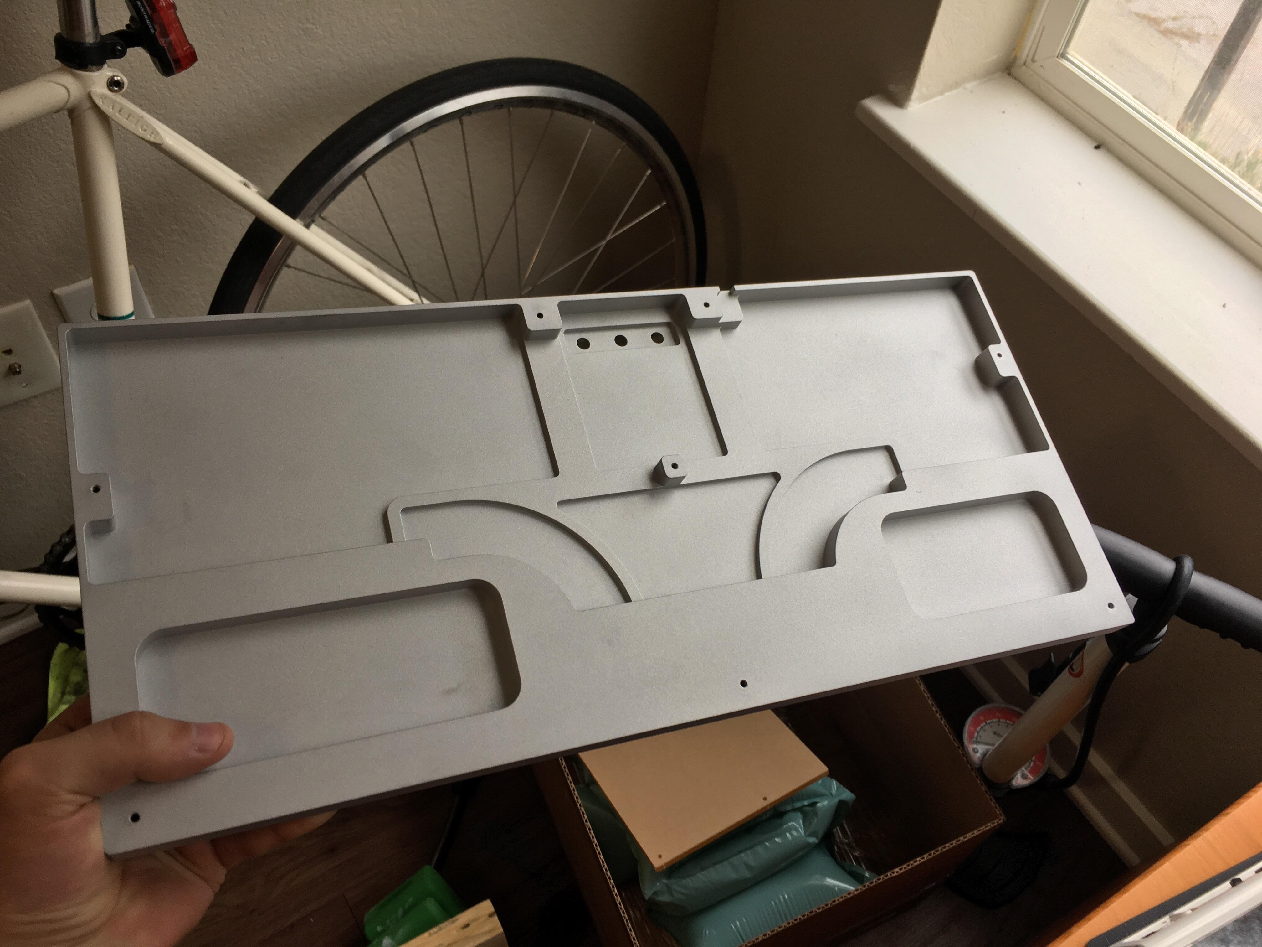
In terms of CAD, the underside of the case was the hardest to make. The “plate” portion of the case needed to be machined down to only 1.5mm thick, so I had to design thicker sections to run throughout the middle of the case to give some support to the plate. Additionally, I needed to add cutouts for mounting the toggle switches, the usb port, threaded holes for screwing the bottom of the case to, weight reduction holes, etc. I also needed to go back a couple times to fix 90 degree inside corners that I’d missed. This was all made much much more annoying by a) not really knowing how to use CAD software and b) FreeCAD running incredibly slow, crashing, having weird bugs, etc. I eventually overcame all of those issues, though, and had a CAD file that I was ready to send out to machine shops for quotes.
One last issue I had with FreeCAD - when it came time to export to a STEP file (a non-third-party-specific CAD file format) of my final design, FreeCAD kept exporting corrupted garbage. I ended up having to export an earlier, non-corrupted version of the case, then sent it to a mechanical engineer friend to finish in Solidworks and re-export. Not great.
Getting Stuff Made
I designed the case to be CNC milled from a single piece of aluminum. This meant minimizing the number of faces that needed to be milled (keep costs low), designing with inside corner radii in mind, etc. The biggest issue with getting the part milled was with the inside corner radii of the actual keyswitch mounting holes.
Cherry MX footprint keyswitches specify a max mounting hole corner radius of 0.3mm. To meet this tolerance, you would need to cut all mounting hole corners with a <0.6mm diameter bit (read: very small & slow & costly). I believe this to be below the minimum bit size of many CNC machine shops. There are ways to get around this by cutting past the corner with a larger bit, but that could potentially affect structural integrity, definitely affects aesthetics, and would’ve required me to mess around more with FreeCAD modifying hundreds of tiny corners. I don’t know if my machinist would’ve done this part for me if I had asked (maybe they have automated tools to do it), but it surely would’ve cost me more. Additionally, certain parts of the case (the mounting holes for the switch stabilizers) were small enough that cutting past the corner in this manner would’ve completely destroyed these small features.
So, I came up with a plan to get around this. Basically, I ordered a case without any keyswitch holes from the CNC milling place, then sent it to a waterjet place to cut the keyswitch holes. This added a lot of time and cost to the process, but allowed me to take advantage of the small kerf of a waterjet cutter to get tighter inside corners for the keyswitch holes. In the end, though, the waterjet could only cut corners with a radius of 0.5mm, but this didn’t affect my ability to mount the keyswitches at all. I think that Cherry super over-toleranced that dimension on their spec sheet - just eyeballing my keyswitches, I was very skeptical that they required such precisely square corners. Worst case, I was prepared to go at the switches / case with a file, but in the future I think I could get away with an even larger radius for the corners.
After getting a bunch of quotes, I went with Partsbadger in Wisconsin for the milling and Colorado Waterjet Company for the waterjet (I wanted to stay local in case I needed to pick-up / drop-off in person). Both companies did a great job with communication and finished the part earlier than the quoted lead time. The Colorado Waterjet Folks even let me + a friend tour the facility when we went to pick up the part. Partsbadger missed some small spots when beadblasting the part, but they were all minor and on the underside in non-visible places. Additionally, I got a quote that was like 30% cheaper from a company that outsources their machining to China, but it was just a little late and I had already paid for Partsbadger, so ended up staying domestic.
Finally, I went through Pololu to get a clear acrylic base lasercut (so you can see the wiring through the underside of the case). This part was cheap and fast, but is a couple millimeters off the dimensions of the rest of the case on multiple sides. I’m not sure if the tolerances are just that much looser with lasercut acrylic or if Pololu did a bad job.
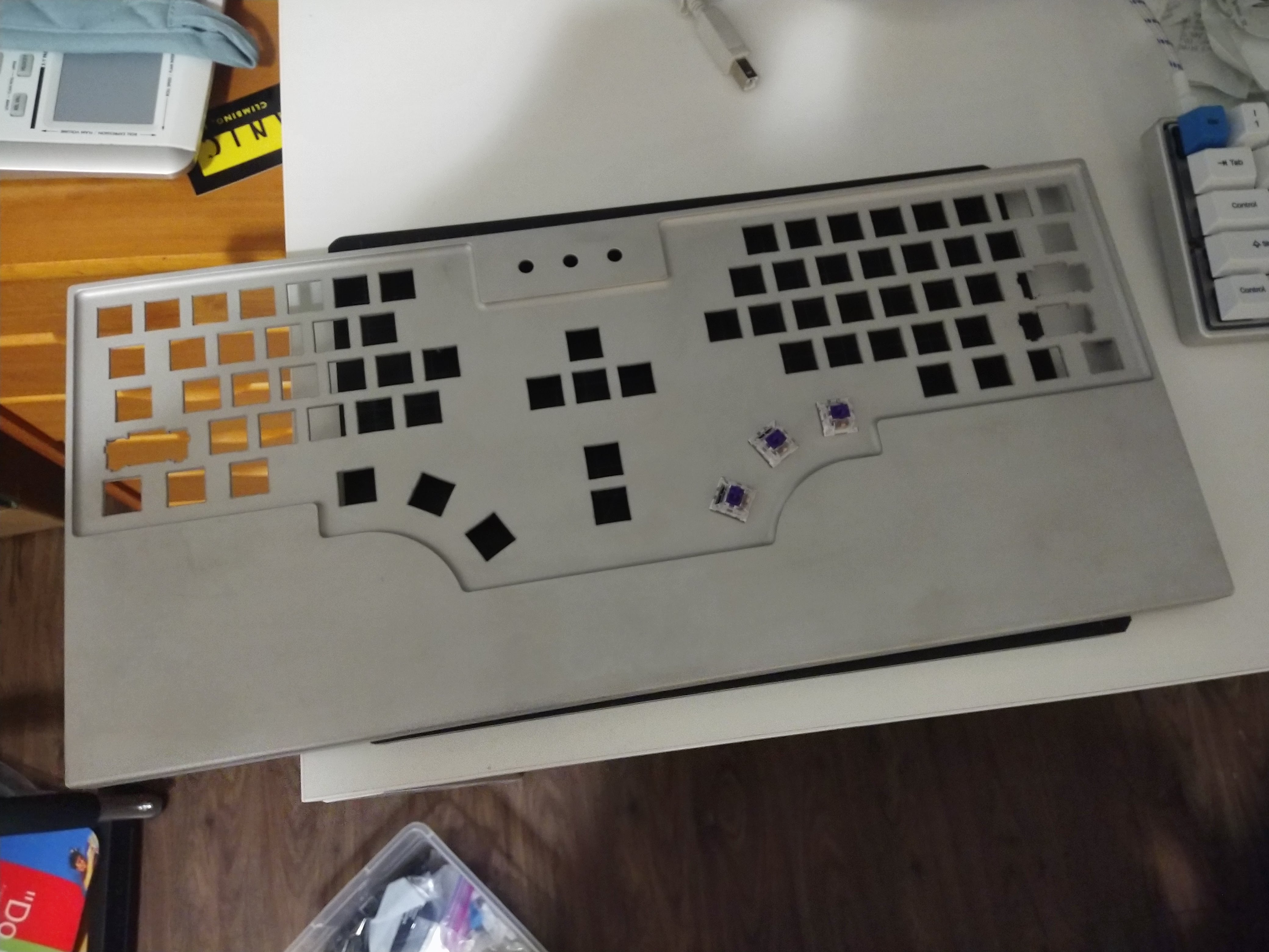
Here’s a top view of the final case with most of the keyswitches uninstalled:
Buying Parts
The biggest decision in buying parts what my choice of keyswitch. I like Cherry Browns, but wanted something heavier and a bit more tactile. I opted for Kailh Pro Purples, which supposedly feel like just that. I didn’t get to try them first, which could’ve been bad because it’s really hard to change out keyswitches on this keyboard, but luckily I like them. I used a spare Cherry Green on the escape key just to mix things up.
I bought my DSA Penumbra keycaps used on /r/mechmarket. Buying used lessens the sting of spending hundreds of dollars on little pieces of plastic. I chose this color scheme to match the solarized color scheme of my terminal (yes, I’m a dork).
I picked up the toggle switches, diodes, Teensy 2.0 microcontroller, and little USB port on DigiKey. I needed to order these before finishing the case so that I knew the exact dimensions of the mounting holes.
Putting it all Together
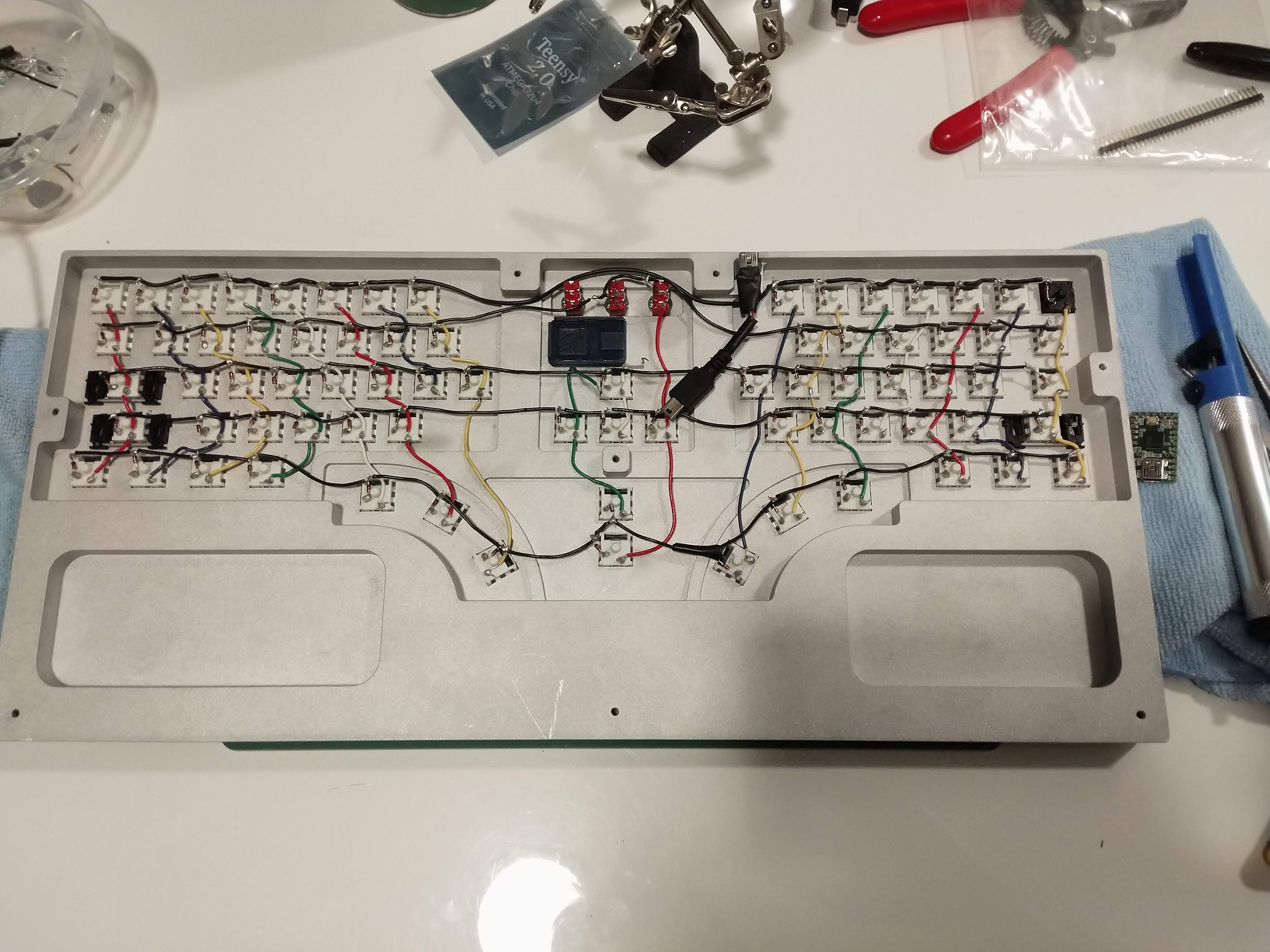
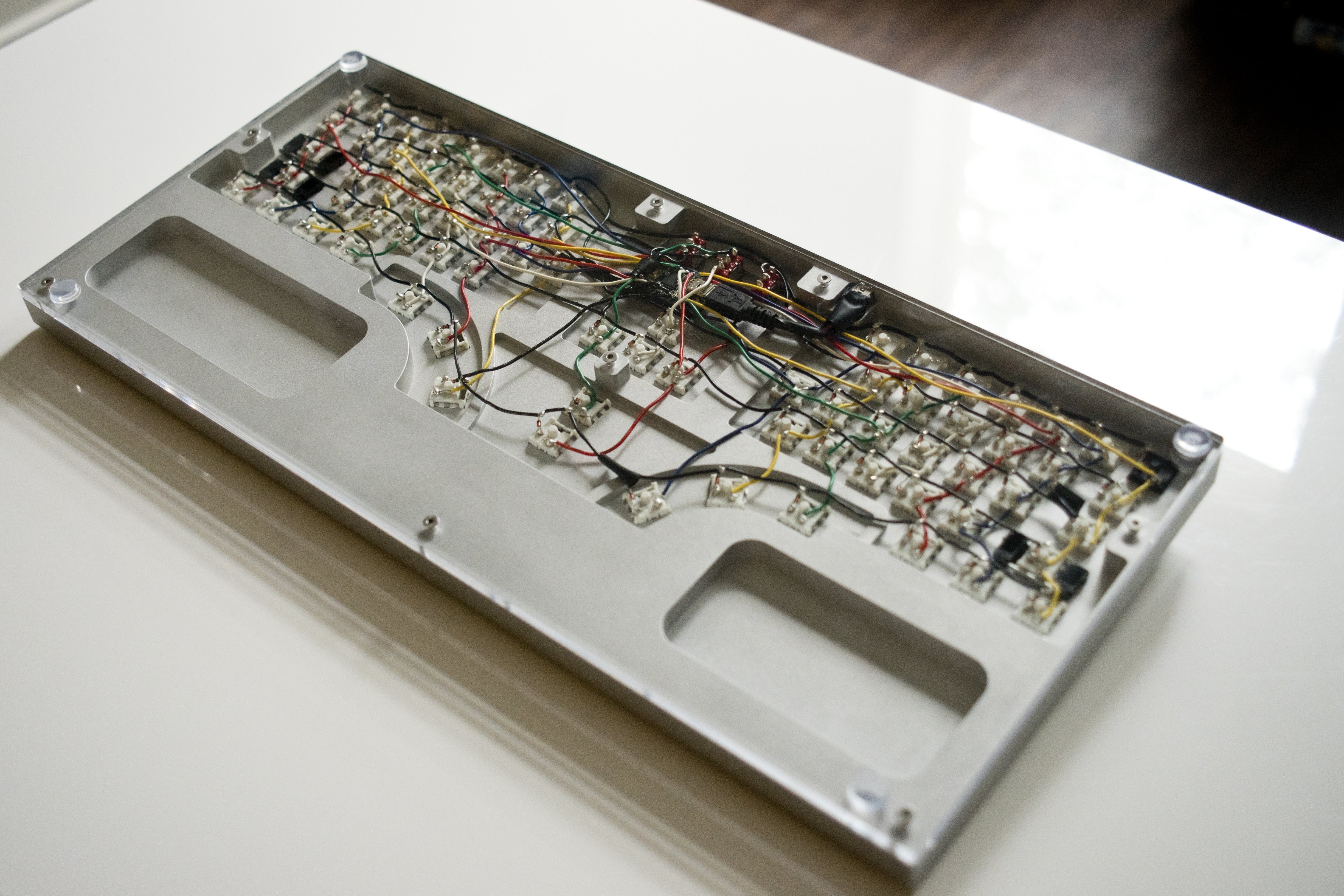
There are lots of good guides to hand-wiring keyboards out there. It’s not hard, just really fucking tedious. One of these wire stripping tools was essential to finishing this process in less than a billion hours. I 3D printed a little Teensy holder to secure the microcontroller to the case, then epoxied both that and the USB port down using some epoxy putty. I stripped a USB cable and soldered it directly to the USB port, then ran that cable to the microcontroller.
Programming the firmware was easy, thanks to an open-source project called QMK. My custom firmware can be found here.
Here are some pictures of my terrible soldering job:
The Future
I had a lot of fun doing this, and hope that people enjoy the project. I’m personally all keyboarded-out for now, but I do think that there are some improvements to be made on the design if anyone is interested in continuing work / making their own Ellipsis. I’ve uploaded all of my CAD files and licensed them under a suitably permissive license in the same repo as the firmware. It’d be really cool to see some Rev. 2 Ellipses in the wild :)
The most pressing thing left to do is to design a PCB for the keyboard. Soldering all that stuff point-to-point was a major pain, and would probably be a huge turnoff to someone who just wants to use the keyboard.
In terms of layout, I’m actually pretty happy with how it turned out. After a couple weeks of use, I’m still adapting to the layout but generally find it pretty comfortable now. The only thing I think I’d change is the spacing between the thumb keys, as you have rotate your thumb quite far to get between them all. I would also make the fillet on the edges of the recessed key area shallower than 90 degrees, as I think that would look better (that’s how the MacBook keyboard is designed).
In terms of manufacturing, I would try to figure out the actual maximum corner radius for MX switches, then cut all the keyswitch holes during the CNC milling process. Having to separately waterjet those holes is slow, costly, imprecise, and overall would be a big blocker to producing a lot of these. Additionally, I would anodize the case in addition to beadblasting it. I didn’t realize that this was possible at the time, and I’ve already scratched through the beadblast-only finish of my case in a couple spots. The case could also use some better weight reduction, though it currently has the added benefit of being usable as a weapon if need be.
I’m not super into lights on my keyboard, but there’s a lot of potential for really cool underlighting with the clear acrylic bottom. There’s also potential for a wood or even metal bottom to the case, which might look better.
That’s all for now!