In a sense, we can’t actually see light.
Bear with me here.
Imagine turning on a flashlight and pointing it at the night sky. An uncountable number of photons stream out of the bulb every second, but you can’t actually observe them directly. It may be hard to even tell that the light is on. Place your hand in the path of the beam, though, and you’ll see a very clear bright spot where the light strikes your skin.
When we perceive light, we’re actually experiencing photons striking us directly in the eye. Conversely, we cannot perceive photons that do not hit us in the eye. That’s why you can’t see a flashlight beam that’s shining away from you, but you can see its light bouncing off of other objects (like your hand.) In particularly dusty / foggy environments you may actually be able to see a light shafts, but only because there are particles in the air scattering photons into your eye.
But what if we could change that? What would it look like if we could see light’s path as it flies through the air? To find out, I built a computer simulation. You can see some of its output below.
A white light shining down from behind a golden sphere.
A white light bouncing between green and blue metallic walls.
In this post, I’ll give an overview of how this simulation works, as well as some demonstrations of how different material properties affect the way objects interact with light.
Implementation Overview
As you may have guessed from the title, the simulation is essentially just a raytracer built using Unity (disclaimer: I work there.) However, instead of sampling the rays that strike each pixel of the camera sensor like a traditional raytracer, this simulation renders the entire path of each cast ray (literally “tracing” the ray. Get it?)
The main simulation loop can be broken up into three main steps: raycasting, tracing, and rendering.
In the raycasting step, we go through a queue of rays and cast them into the scene. This step is used to figure out where each ray hits an object and terminates (if at all). For any rays that do manage to strike an object, new rays are created and enqueued for future casting. The new ray parameters are based on the angle of reflection and various material properties (I’ll get into specifics about this later). Finally, if there’s space left in the queue, it is topped up with new rays randomly shot out of light sources in the scene.
The raycasting step happens on the CPU, and uses the Unity physics system for actually calculating the ray hitpoints. That means that reflections are based on object colliders rather than their actual mesh geometry. In addition to performance issues, doing this step with the physics engine is problematic because mesh colliders are limited to 256 triangles by Unity. I got around this by only using primitive (sphere, box, etc.) colliders and highly simplified mesh colliders. If I were to do this for real, though, I’d look into GPU raytracing support and stay far away from the physics system.
In the tracing step, info about all the cast rays (start, end, color) is passed to a GPU compute shader. This shader’s job is to update two different screen-sized textures - one for the average color and one for the total brightness of all rays that have crossed each pixel. The shader runs on a per-pixel basis, checking if each ray cast during the simulation passes through the given pixel. If it does, that ray’s color is used to update the pixel’s average color and total brightness values. This shader also checks the depth of each point along the ray against the scene depth buffer at that position, so that occlusion of rays by scene objects works as expected.
Finally, rendering the image is as simple as taking the output of the tracing step, scaling all the color values based on their total brightness values, then drawing to the screen. I wrote a shader to find the brightest pixel in the image and scale all brightnesses logarithmically proportional to that max. In hindsight there are probably many superior ways of doing this. I think this process of going from high to low dynamic range is generally called tonemapping, but I didn’t know that at the time.
Here’s an example of a simulation running slowly, casting a single ray at a time. I’ve overlayed a faint image of what the scene looks like with a “normal” camera so that you can see what all the rays are bouncing off of. Note that the “normal” view has had an extra light added to it so that objects are visible - in the actual simulation scene, it’s just a light in the bottom left, along with two cubes and a monkey head.
And here’s the same simulation sped up and casting multiple rays per simulation step:
One thing worth noting is the way that overlapping rays are blended. For most of this simulation, I tried to stick to physical precedent, but there isn’t really one here. Are light rays solid? Translucent? Do they have a thickness? The method I ended up using is essentially a per-pixel weighted average of all the rays that have passed through it, but it would be interesting to try some different blending algorithms to see how things are affected.
Material Properties
For me, the most interesting part about this project was learning about how different materials reflect light. In school, you’re taught that “the angle of incidence equals the angle of reflection” - but there’s much more that goes into creating realistic computer graphics.
Color
The simplest and most obvious property is material color. Physical materials reflect different wavelengths (colors) of light at different rates. To simulate this, our virtual materials define a “base color”. When a ray strikes an object, the color of the reflected ray is set to the base color multiplied by the color of the incident ray. The logic here changes a bit for non-metals, but we’ll get to that in a later section.
Roughness
In the real world, even seemingly flat surfaces have tons of microscopic scratches and ridges. These little peaks and valleys change the angle of incidence of any given ray, meaning that a reflected ray may end up shooting in a direction that’s not exactly mirrored about the overall surface normal.
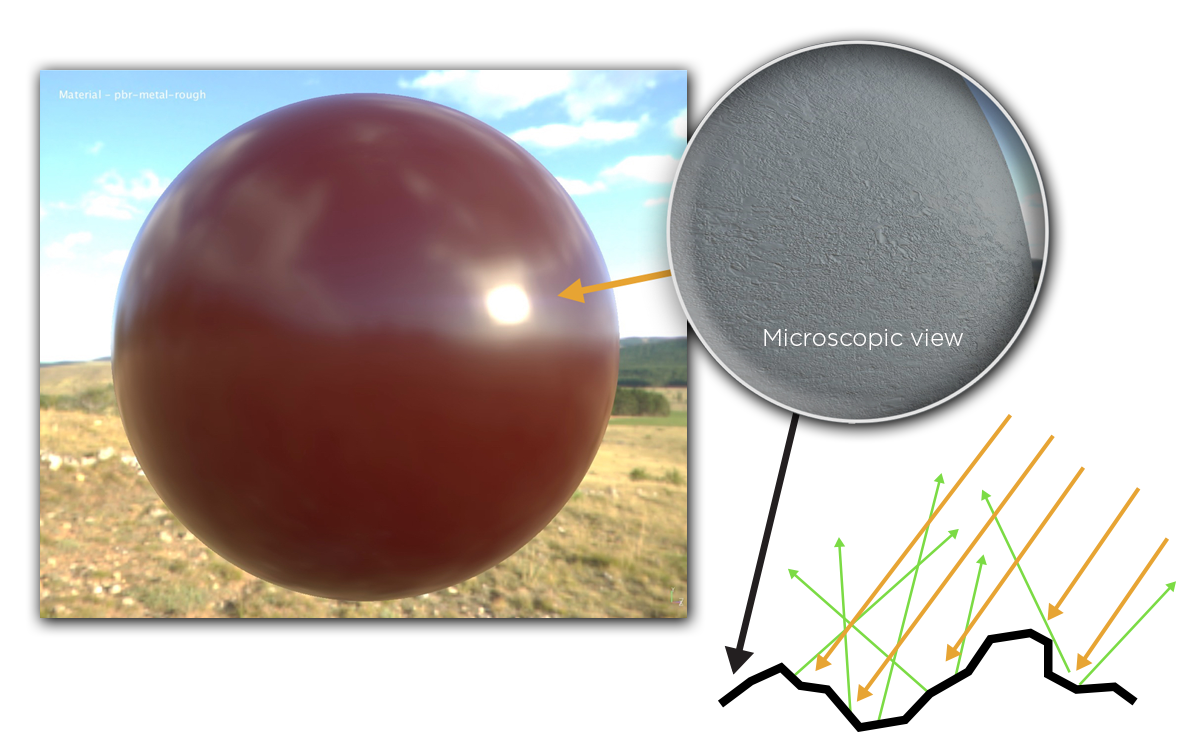
Source - Adobe PBR Guide
In the above image, you can see an example of this effect. Though the surface of the sphere is macroscopically smooth, the microscopic ridges cause the incoming rays (orange arrows) to be reflected in somewhat unpredictable directions (green arrows). This is why the reflections of the clouds and scenery on the red sphere are a bit murky rather than being clearly defined. The surface roughness adds a bit of “fuzziness” to the sphere’s reflections, blurring sharp lines and features.
Here you can see how a rough, golden, metallic plate is modelled in the simulation. During the raycasting step, some gaussian noise is applied to the surface normal at each ray contact point. This causes the reflected rays to scatter randomly - much like the reflected rays shown in the previous diagram.
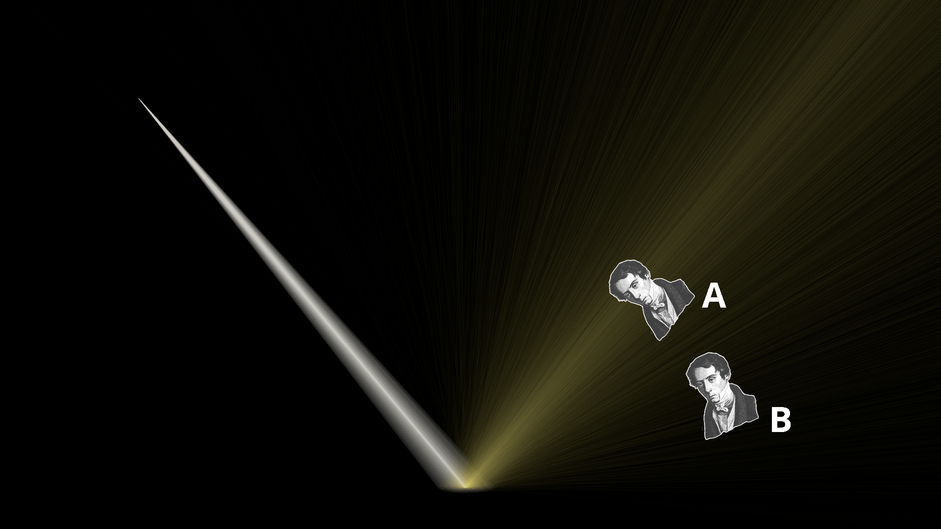
If we superimpose two hypothetical observers onto the simulation, we can reason about how each of they each perceive the reflection from the rough plate. Observer A is situated right along the path of the “ideal” reflection (where the angle of incidence equals the angle of reflection). As such, they experience a bright and wide golden reflection from the plate. Observer B is positioned at a lower angle, on the fringes where fewer rays are scattered. Therefore, Observer B will see a much dimmer reflection than Observer A.
Here’s the same simulation, but with a perfectly polished blue metal plate. Because there’s no surface roughness at all, each ray is reflected perfectly such that its angle equals the angle of incidence. This results in a very tight, focused beam of reflected light.
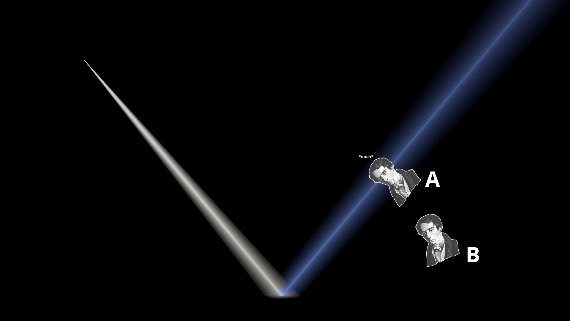
When we overlay Observers A and B in the exact same spots as before, we can see that something different has happened. Now, Observer A is getting the full force of the reflection. Their eyes are effectively absorbing as much energy as if they were staring directly into the light. This is probably very unpleasant.
Observer B, on the other hand, cannot see any reflection at all. Because the reflections off of the perfectly smooth material are so focused, it means that you need to be in a much more specific position to see any reflected light at all. As a sanity check, here is how a “normal” 3D renderer displays these materials from each Observer vantage point:
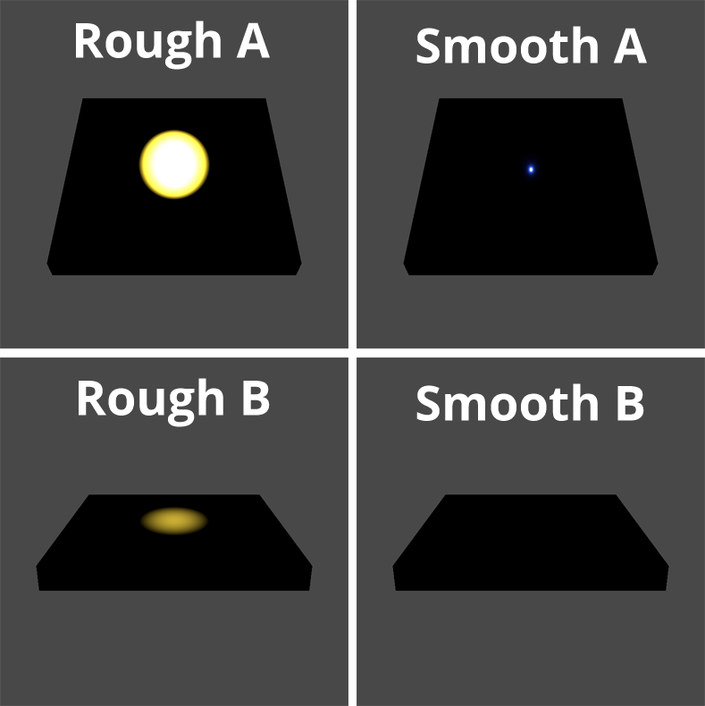
We can see that everything is exactly as predicted from our simulation - wide, fuzzy reflections from the rough plate that are dimmer from Observer B’s position, and a hyper focused reflection from the smooth plate that disappears entirely for Observer B.
Metalness
Note that up until this point, we’ve only been talking about metallic materials. That’s because there’s a fundamental difference between the way that metals and non-metals interact with light.
To understand why, imagine turning on a flashlight and putting a piece of aluminum foil over the bulb. No light will escape. Do the same with a sheet of wax paper, though, and you’ll be able to see light shining through - even though the two materials are roughly the same thickness. This is because metals fully absorb all the light that they don’t reflect, whereas nonmetals can allow light pass through. Of course, most objects we see are not as thin as a piece of paper, but this principle still holds. Thick, non-metallic objects allow light to penetrate the surface at a microscopic level. This seemingly minor effect is primarily responsible for the visible differences between metals and non-metals.
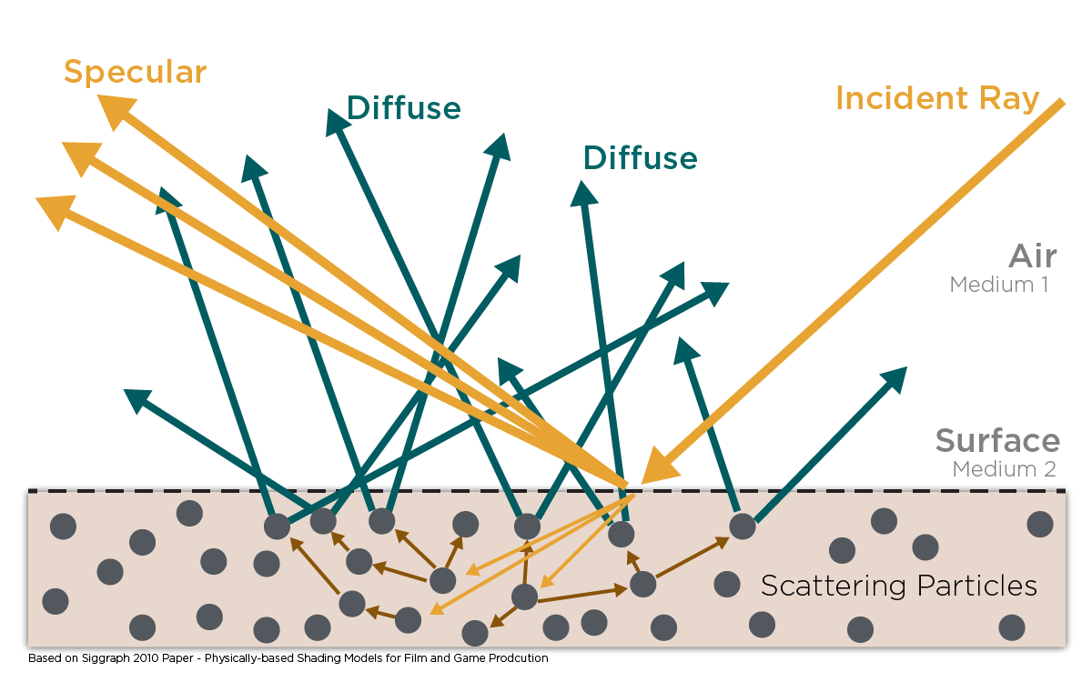
Source - Adobe PBR Guide
The above diagram portrays light striking a non-metal. The rays labeled “Specular” are the ones being reflected directly off of the surface. Specular reflections behave in the way we described in the roughness section above, and exist in both metals and non-metals
The main difference between metals and non-metals lies in the rays labeled “Diffuse”. Notice how the incident ray in the diagram actually penetrates the surface of the material. When a ray penetrates like this, it bounces around on the material’s constituent particles until it’s either fully absorbed as heat, or until it manages to bounce back out of the surface of the material and into the environment. If a ray manages to exit the material’s surface, we can assume that it has bounced around so much that it’s effectively travelling in a new, random direction.
Here’s a simulation of lights striking a pink plastic plate (left), and a white metal plate (right.) The first thing you’ll probably notice is that the light striking the pink plastic is being sprayed haphazardly all around, whereas the light striking the metal is sent in a very specific direction. This is because the plastic is non-metallic. Incident light is able to penetrate its surface, bounce around, and diffuse in completely random directions. The metal, on the other hand, absorbs all light that isn’t immediately reflected, and is therefore only able to produce a specular reflection. The implication for observers is that the pink rays from the plastic can be seen from all angles, and are a relatively even brightness regardless of viewer position. On the other hand, metal varies wildly in brightness based on how close an observer’s eyes are to the center of the specular reflection.
It’s worth pointing out that non-metals still create specular reflections. In fact, you can see this in the simulation. The slightly brighter orange streak in the bottom left is the plastic’s specular reflection, and an observer looking directly at those rays would see a bright spot (just as we saw in the metallic examples.) This is why some materials (polished marble, glossy plastic) can still look “shiny” while still being distinctly non-metallic. If you can reduce a material’s surface roughness enough, it’ll develop the same sharp, specular highlights that polished metals have.
Fresnel Effect
The final thing I want to show is a really cool phenomenon called the Fresnel Effect.
In short, the Fresnel Effect describes the tendency for surfaces to get more reflective as you get closer to parallel to them. You can see this effect when looking at a wide variety of surfaces, but I’ll use the surface of a lake as an example here. When standing on the shore and staring at the water, the closer to your feet you look, the closer to perpendicular your viewing angle will be to the surface, and the less reflective the water will appear. Staring out farther from shore, the opposite is true, and the water will appear almost mirror-like. You can see this in the image below. The sand beneath the water can be seen near the bottom of the image, but not farther away, where the reflections of the mountains and sky can be seen instead.

The Fresnel Effect is described mathematically by the Fresnel Equations, which calculate the ratio of light that is reflected when striking a surface. The formula returns higher reflectance values for incident rays that are closer to parallel with the struck surface, hence the Fresnel Effect. In the case of the simulation, we compute this reflectance value (or rather, Schlick’s Approximation) every time a ray strikes an object. From there, we cast a new ray for the reflected component and scale its intensity based on the computed value. This ray constitutes the specular component of the reflection.
By subtracting the reflectance value from one, we get the amount of incident light that is transmitted into the struck surface. As discussed in the previous section, this component is entirely absorbed by metallic materials. For non-metallic materials, we scatter a second ray in a random direction and scale its intensity by the transmittance ratio times some constant positive factor that’s less than one (to simulate loss of energy from absorbtion). This constitutes the diffuse component of the reflection.
Above, you can see three lights striking three identical planes made of a blue non-metallic material. You can see that each object reflects both diffuse (blue) and specular (white) rays, but the ratio of blue to white is different for each object. The closer the object gets to being parallel with the light source, the more rays are reflected specularly rather than entering the material and being scattered as part of the diffuse reflection. That’s the Fresnel Effect in action.
Closing Thoughts
This was a really fun project to work on. I had some familiarity with material properties before, but I think that seeing how light bounces around “behind the scenes” really helped deepen my understanding. Now I often find myself looking around at various surfaces, trying to follow the path of light through the environment.
If you’d like to mess around with the simulation yourself, you can get the Unity project source on github. It might be a fun project to try converting it to use the GPU more effectively, so that rays could be cast more quickly. It’d be cool to see these sorts of simulations in realtime with moving objects and cameras, but that would require quite a big performance upgrade.
I’d also like to see if someone can use this to get good visualizations of more complex scenes. When trying to set up scenes with more than 2-3 light bounces, I found the results were often way too visually cluttered to take anything meaningful from them. Maybe the blending algorithm needs to be reconsidered, or some layer of realtime interactivity needs to be added (eg. controls to show only light bounce 2 or bounces from object X.) I also have full texture sampling support set up for materials, but in practice couldn’t find any demo scenes I wanted to show that made use of that.
Have fun!