Lately, I’ve been messing around with recording music. I played guitar occasionally when I was younger, and recently started again in order to create a soundtrack for some videos I working on. One thing that really bothered me about recording guitar specifically was that I would always need to take my hands off of the instrument in order to push the record button, then quickly return to playing position. This often meant spending more time pressing buttons to stop and restart recordings than actually playing. To remedy this, I decided to buy a MIDI foot controller for hands-free recording controls.
Until I looked at the prices… This is one of the top rated USB MIDI foot controllers on Amazon, and it’s $80! For a little metal box with three switches! Outrageous!
Looking now, I see that you can find some cheaper models used on eBay and the like, but supply is scarce, and there weren’t any available when I was shopping around. Even if I could’ve bought these cheaper models, though, I would’ve still opted to build my own. I was convinced that I could build something with more features for way less than $80, and set out to prove it to myself.
Desired Features
For this project, I was aiming to build something in the $40 range with the following features:
- At least two footswitches. One to start recording and one to stop.
- An expression pedal. Being able to control analog parameters is always nice, and is a feature not present on any of the cheaper commercially available options.
- Multiple control banks. Being able to change what each control does on the fly is extremely important. A box that can do 3 things is useful, but a box that can do N * 3 things is N * useful.
Finding an Enclosure
Even for someone with only a rudimentary understanding of electronics (like myself), building a USB MIDI controller is not very difficult. Building one that feels good to step on, on the other hand, is a little more challenging. My first thought was to buy a metal project enclosure and drill some holes in it for mounting components. However, I didn’t have faith in my ability to build a mechanically sound expression pedal from scratch, so I decided that this would not be a good idea.
After some searching, I realized that I could buy an existing non-MIDI guitar pedal and simply convert it to output MIDI. This would include the benefit of having all switches and potentiometers already included and wired up! I picked up a used Digitech RP200a for $30 ($15 + $15 shipping) because it had all the controls that I needed and seemed to be sturdily built. I specifically bought a broken pedal to save on costs and ensure that I wasn’t destroying something perfectly functional. The unit I bought supposedly made a buzzing noise and would not output audio, which didn’t matter for my purposes. All I cared about was the physical condition of the buttons and analog inputs, which I assumed were not affected by this audio problem.
First Impressions
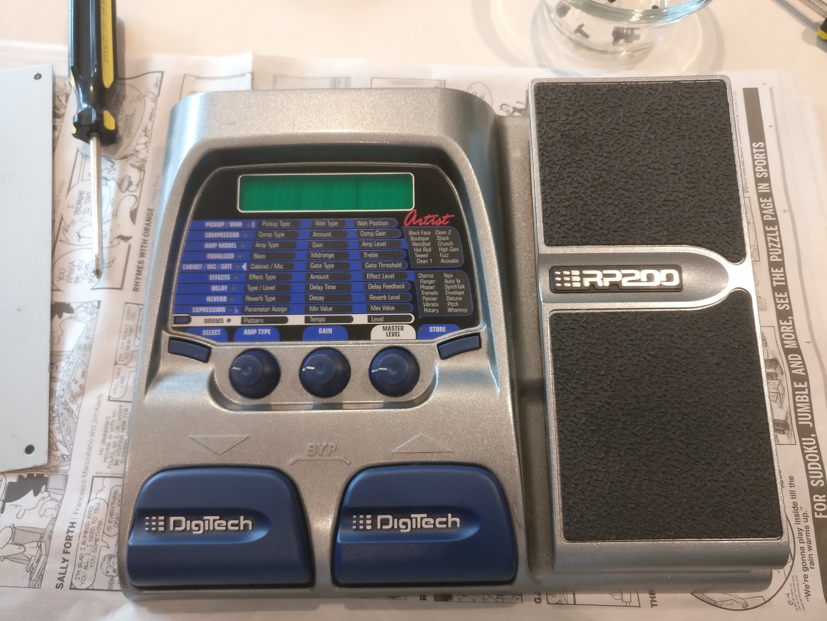
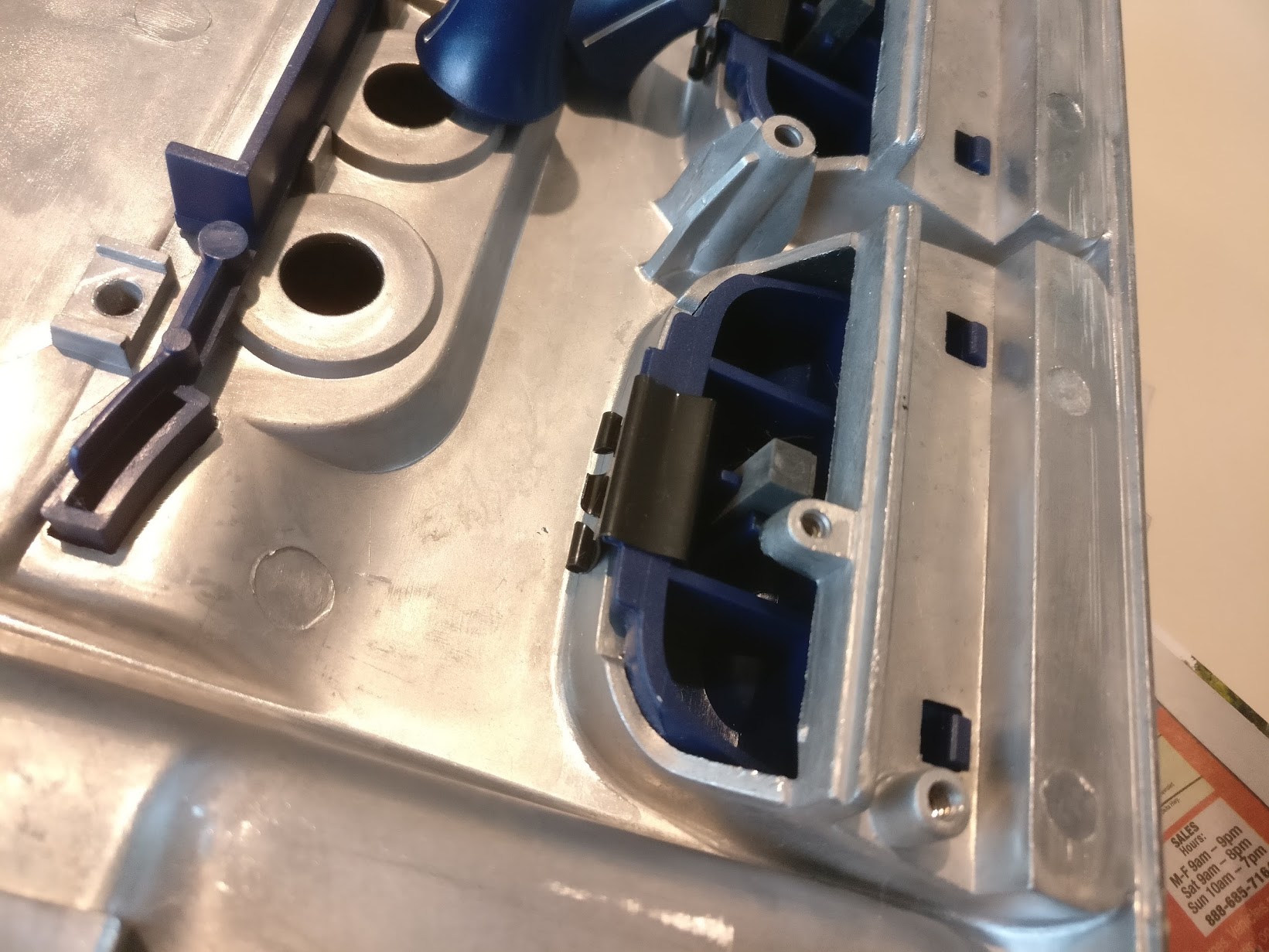
When my unit arrived, I was pleased to see that it was in perfect physical condition. It looks like the previous owner barely used it. Overall, I was impressed by the build quality. The enclosure is sturdy and has a decent heft to it, there’s no play in the expression pedal, and the knobs all have a pleasant amount of resistance. The one thing I was a little disappointed by was the feel of the footswitches. They’re a little mushy and lack tactility, but for $30 I can’t really complain. I was amused to see that the footswitches are actually held on by binder clips… Anything to cut costs, I guess.
Understanding the Electronics
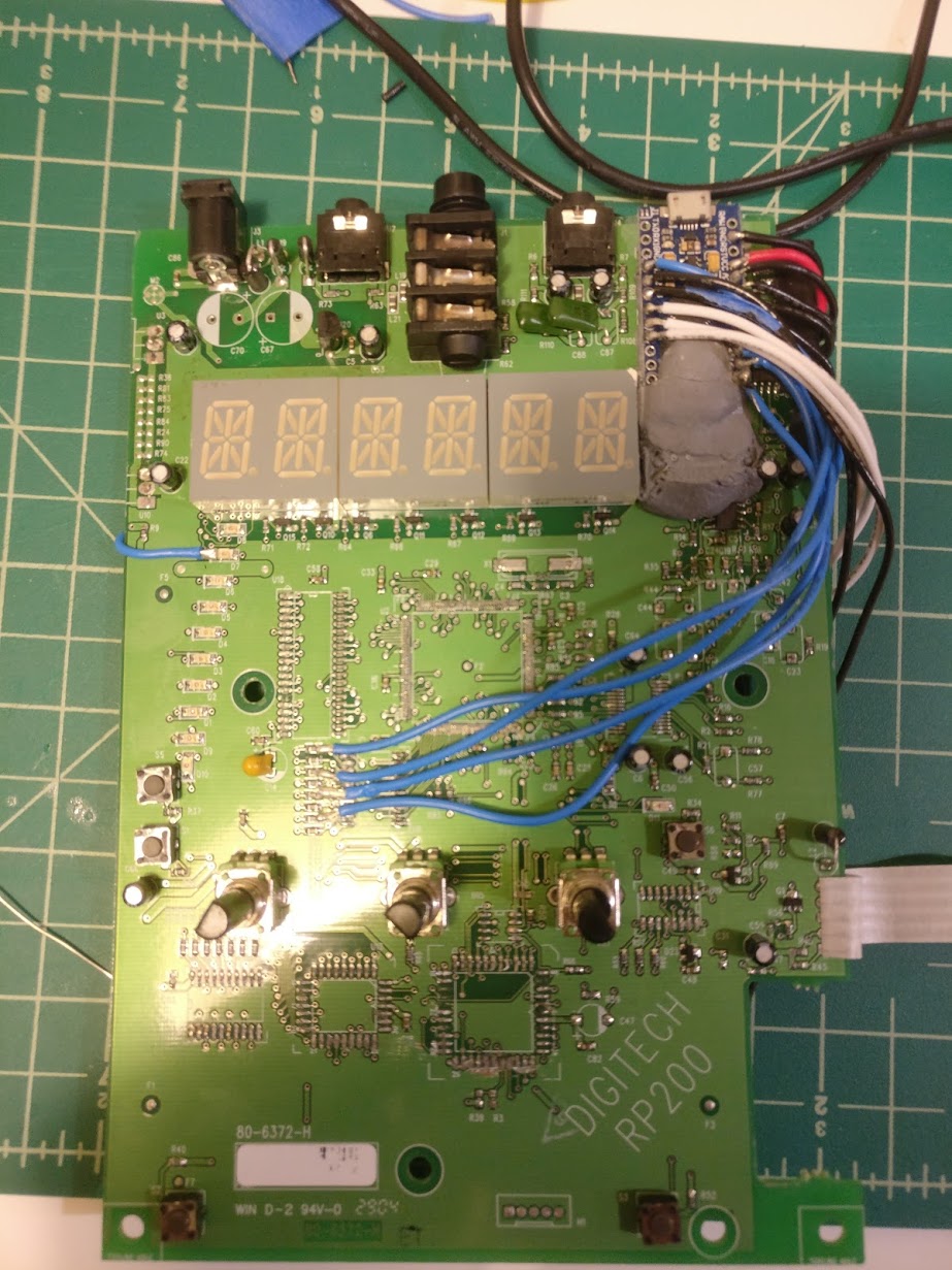
I don’t really know what I was expecting the pedal’s PCB to look like, but it ended up being a lot scarier and more complicated-looking than I had hoped. As mentioned before, I don’t know much about hardware. I’ve programmed microcontrollers and done some soldering, but my understanding of how commercial electronics work is limited to say the least. With that being said, I like to think that I learn quickly, so I was happy to take on this challenge.
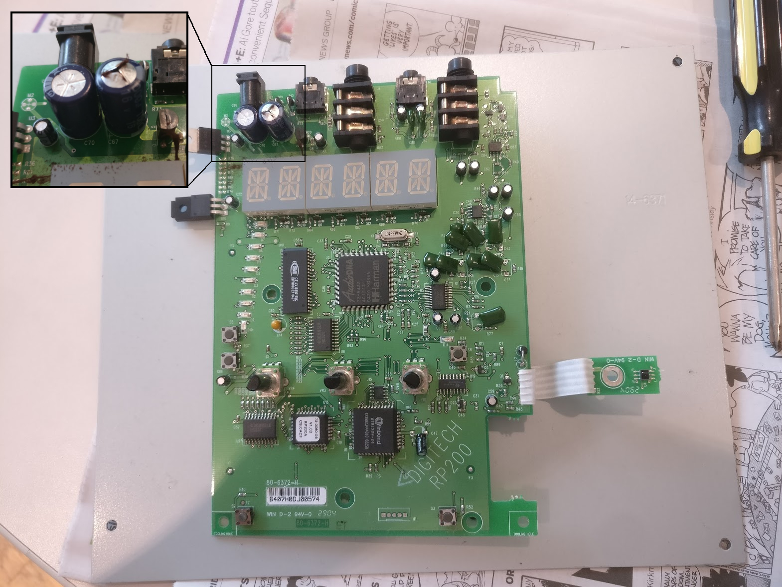
The first thing that I noticed was the blown capacitor near the power in port on the board. I assume that this was the cause of the buzzing noise the original owner described. If this was actually the only thing wrong with the board, I’m guessing I could’ve replaced this capacitor and have had myself a good-as-new effects pedal at half price.
The next thing I noticed was the mysterious daughterboard that was being used to read the expression pedal. It was easy to figure out the pinouts of the pots and buttons on the main board, but I had no idea how to read values from this daughterboard. The little black sensor was too small to have a model number on it, so I couldn’t depend on that. After some thought and googling, I guessed that this sensor was actually two components packaged together - an LED and a photoresistor. I didn’t know how to really test this theory yet, but it did turn out to be correct.
From here, I used a combination of googling part numbers, probing with a multimeter, and following traces to figure out what each part did and how they were connected. The following observations greatly helped me with figuring out how to hook everything up to an Arduino, and can hopefully be applied to any future electronics projects I do:
- Components receive power from either the 3.3V or 5V regulator on the left side of the board. The large, copper layer covering the front of the board goes to ground and is known as the “ground plane”. This was a huge discovery for me, because it meant that I could power everything without running wires between the microcontroller and individual component power/ground pins. For a while, I was confused because the 5V voltage regulator was stamped with a 3.3V model number. However, when attempting to power the board on by connecting 3.3V power to these pins, everything turned on, but the LEDs were incredibly dim. Changing this to 5V made everything better, and proved to me that the unit was indeed functional.
- The large, square AudioDNA chip in the center of the board was its “brain”. The smaller square chip near the bottom handled input and other peripheral functions. Presumably, the AudioDNA chip handled everything pertaining to audio processing. There must have been some link between the microcontroller and the AudioDNA chip for sending control readings - potentially via serial.
- The 16-segment displays and LEDs were controlled by a pair of edge-triggered flip-flops. I believe that these were used because the microcontroller only had enough pins to control a small amount LEDs at a time. In order to drive all 16-segment displays and the various LEDs on the board (which share a ground), I think the controller would set all inputs to the flip flop, trigger it to update its outputs, then quickly changed which segment/LED group was grounded.
- The inputs and outputs at the top of the board are largely disconnected from everything else. This made sense, in my mind, because the logic chips would need to run at a lower voltage than the 9V input and the audio inputs / outputs. This also explained all the random big capacitors spread around the area, which were probably for regulating the input power.
Putting it all Together
Once I was confident that I knew how everything worked, I began chopping off components. I started by removing the AudioDNA chip and the microcontroller, as I didn’t want them interfering with any of the LEDs. I wish I had been able to remove them gracefully, but without access to a hot air station or something similar, I found that the best way to get them off was with a dull knife and some elbow grease. I desoldered the 3/4” input jack and used some epoxy putty to stick my Arduino Micro in its place. With a little filing of the enclosure, the Arduino’s USB port was easily accessible through the 3/4” jack’s original hole.
From here, I soldered wires between the ground, 3.3V, and 5V pins of the Arduino and the relevant pins where the (now removed) voltage regulators once were. I then held a loose wire in place as I tested the Arduino’s ability to read from the potentiometers and buttons. I used a similar method to test lighting of different LEDs.
This proved to be a terrible idea, as this imprecise process caused quite a few accidental shorts which proved fatal to my poor Arduino. To ensure that I would have backups in case of future accidents like this, I ordered three new Arduino Pro Micros. These were cheaper, but had less i/o than the regular Micro. Once these arrived, I made sure to do all my testing with wires soldered onto the PCB on one end and plugged into one of the Arduinos via solderless breadboard on the other. Each time I needed to test anything, I checked for shorts before powering the unit on. All three of these new Arduinos survived :)
At the time, I thought that my first Arduino had died because there were other components on the board were drawing too much current. Now I’m pretty sure that it was because of all of the shorts, but it could be that something was drawing extra current as well. Just to be safe, I ended up removing pretty much all components on the board that were not needed for input or output. Originally, I was planning on keeping the flip-flops in place to drive the 16-segment displays, however, I realized that my soldering skills were nowhere near good enough to get a wire between each of those little pins and the Arduino, so they were removed like everything else. I really wish I could’ve used them for display, but it was just too much trouble. The four LEDs I ended up using instead are plenty to display the pedal state.
There were only three small hiccups during this process. The first was pretty minor, but I realized too late that the new Arduinos I had bought did not have 3.3V power. Luckily, the only things left on the board hooked up to 3.3V power were the buttons - and it didn’t really matter what voltage those were run at. So, I ran a wire between the 3.3V and 5V pins on the PCB and everything worked fine.
The second and third problems, both involving the expression pedal, took a little more debugging. At first, I was getting weird, noisy readings from the photoresistor. At some point during the build, I must’ve bent the ribbon cable connecting the daughterboard and the main board, snapping the connections inside. After replacing this cable with wires, the readings stabilized, but were consistently far too low to be usable. I had a hunch that I had burned out the infrared LED during my experiments, and used my phone camera to confirm that it was not lighting up. This was upsetting, and I even started looking for surface mount LEDs to replace it with. Luckily, though, I discovered that it was not burned out, but had simply been disconnected from ground at some point during the component removal process. The readings from the sensor are still not ideal, though. It only reads 1.5V with the expression pedal backed off all the way, which means that it can’t take advantage of the full resolution of the Arduino’s analogRead(). Over time, its dynamic range has narrowed even more, which leads me to believe that I might be driving the LED too hard and slowly killing it. I wonder if I clipped some sort of necessary resistor at some point, or if I simply ran the wires to the wrong places.
Conclusion
Thanks to Arduino’s MIDIUSB library, writing the firmware was simple - it only took me a couple hours. I ended up using two of the knobs for changing footswitch and expression pedal control banks. The two extra buttons on the controller are used to change each footswitch between toggle and momentary mode. Finally, the LEDs indicate whether or not each footswitch is in toggle mode, and if it is currently enabled.
The expression pedal doesn’t work that well. I’ve spent a while messing with it’s curve and sensitivity, but a lot of the problem involves the fact that it just doesn’t have great resolution, especially when the pedal is pressed almost all of the way down. Also, the readings are jittery and unpredictable due to the fact that the sensor’s dynamic range is constantly changing. It’s definitely usable for things that don’t require a lot of precision, but not ideal. There are a couple things I could improve this, like adding auto calibration and some more filtering, but I just don’t use the expression pedal enough for it to be worth it. If this changes in the future, I might look into converting it to use a potentiometer or something more reliable.
There’s also the issue of cost. For someone who knows what they’re doing, this project could easily be done for less than $40, maybe even less than $25 with some eBay luck. For someone who’s prone to destroying microcontrollers, it’ll cost a little more, but still far less than commercially available options with similar feature sets. There is, of course, the opportunity cost of having to make it yourself, but that’s not a problem if you enjoy doing it!
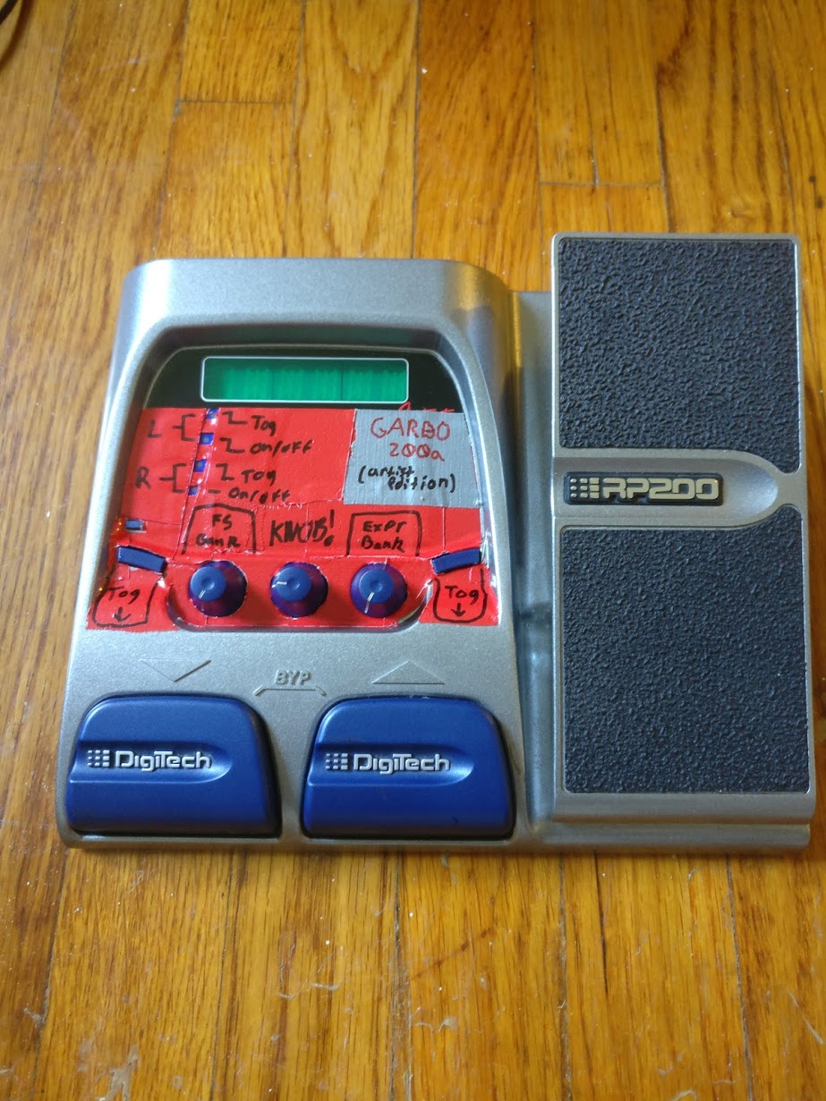
Other than that, I’m really happy with how it turned out. It’s incredibly ugly, but that’s because I decorated it at 04:00 after many hours of coaxing it to life. I kind of like how it looks though, and I think the name I came up with in my sleep-deprived state is really fitting. So, without further ado, I present the Garbo 200a - a cheap, sturdy, MIDI foot controller. I think it will see a lot of use over its lifetime.